The MSI X299 Tomahawk Arctic Motherboard Review: White as Snow
by Joe Shields on November 20, 2017 8:00 AM EST- Posted in
- Motherboards
- MSI
- M.2
- USB 3.1
- X299
- Skylake-X
- Tomahawk
- Tomahawk Arctic
Visual Inspection
Obviously, the first thing that jumps out at most users here is the white(ish) board. I say "ish" because it is more of a very cold temperature white where it has almost a slight blue hue to it. A white motherboard can be polarizing in a build theme, but the regular MSI X299 Tomahawk (non-Arctic) is the same style except black. The heatsinks and shrouds are more of a warmer white color and have the Tomahawk name along with MSI, X299, and Arsenal branding. The large chipset heatsink runs through the PCIe area and is used as a heatsink for the first M.2 slot. RGB LEDs are found on the back of the motherboard only, but more can be added via a single RGB header located on the bottom left side of the board. It supports the standard 5050RGB multi-color LED strips with a maximum power rating of 3A(12V).
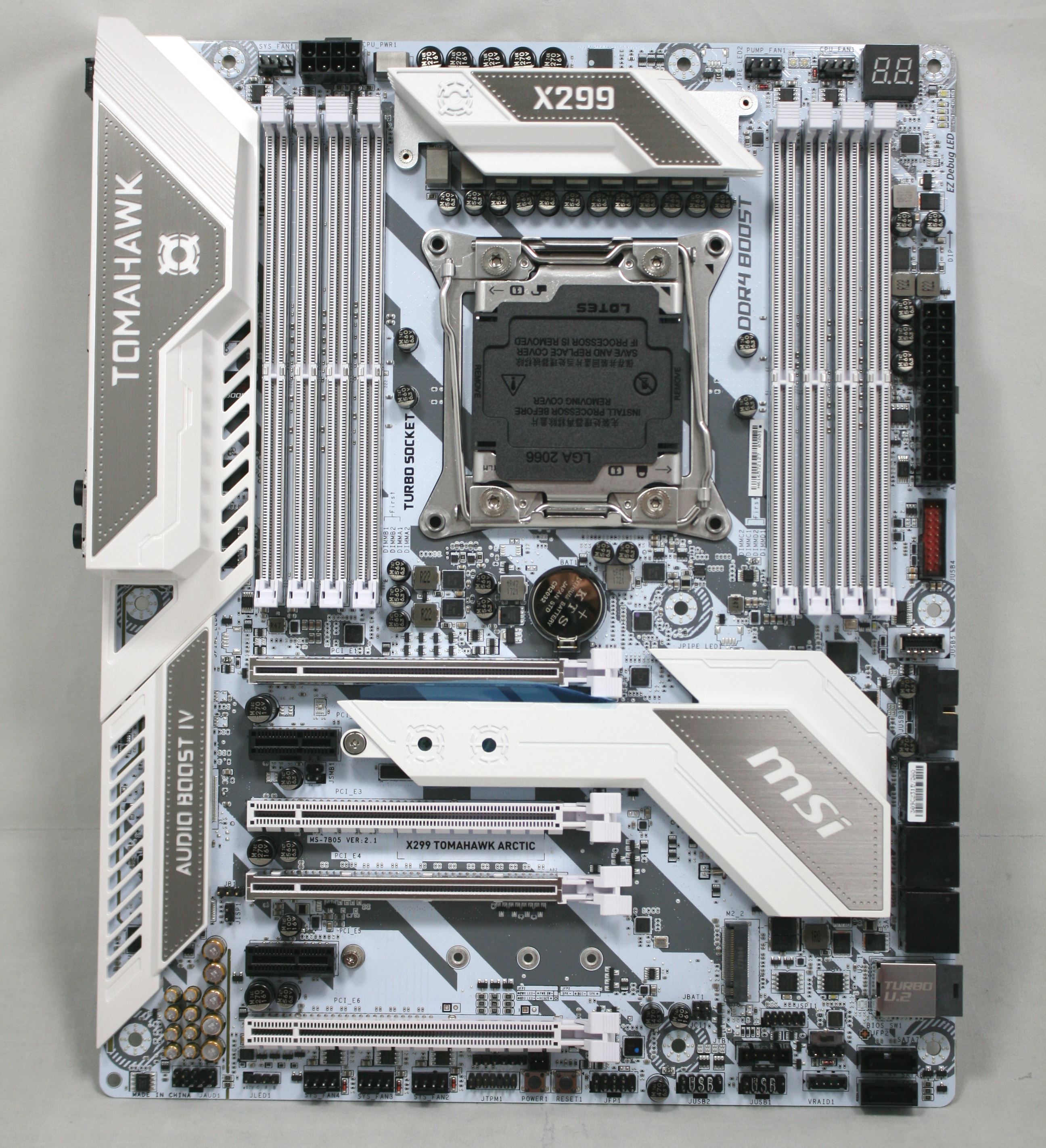
Onboard headers are scattered around the board with most located across the bottom. There are six 4-pin fan headers with three located across the top: the first by the 8-pin EPS power header, with the second and third (the pump fan and CPU Fan1) are to the right of the VRMs above the DRAM slots. The headers can be placed in PWM Mode or DC Mode, controlling three or four pin fans. MSI documentation did not appear to mention if any of these headers output more than the typical power (~1A/12V). Also, each fan header has a red LED next to it which will light up when a fan is connected to the header.
The socket area is a relatively clean with capacitors to each side. There are several components close to the bottom of the socket, however, although that might only be of concern to extreme overclockers. The contrast of the whiteboard and black parts gives the board a busy look. It isn't to say it looks bad, but the white board will tend to be polarizing for themed builds, as opposed to a more theme agnostic black.
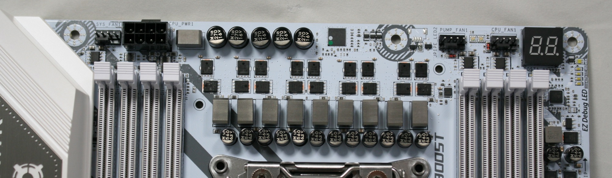
By the looks of it, we see a 9-phase VRM by count, but digging a bit deeper we see it is really 4 phase and doubled. Controlling things is an International Rectifier IR35201 8-channel controller working with Nikos PK616BA and PK516BA MOSFETs. Phase doubling duties are handled by four Infineon IR3598 MOSFET drivers. Delivering power to the VRMs is an 8-pin EPS 12V connector located above the left set of DRAM slots while a 24-pin ATX connector takes care of the rest of the board. During testing, the VRM heatsink did get warm, but I did not notice throttling while testing. It is worth noting that most new X299 motherboards are now equipped with dual 8-pin EPS 12V connectors to help spread the load.
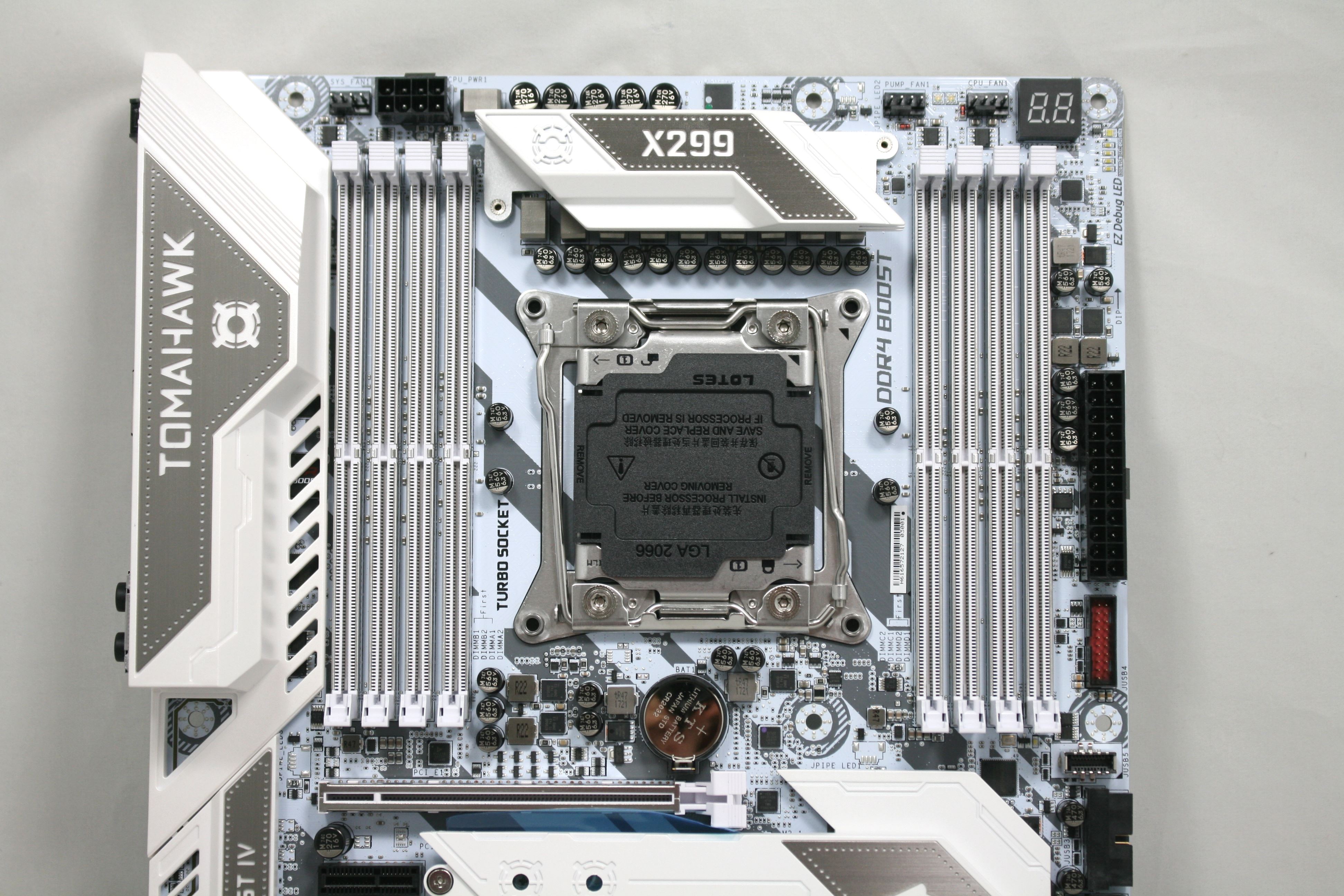
The DRAM slots are all reinforced and use a one latch system to lock the sticks in place. Memory capacities up to 128GB are supported with speeds up to DDR4-4133 in quad channel listed on the box, as well as DDR4-4500 in dual channel operation. There are also LEDs above each DRAM slot that when populated are lit up white.
On the top right is a two-digit debug display, showing POST codes and temperatures, along with the EZdebug LED which lights up while in specific parts the boot phase. There are LEDs for Boot, VGA, DRAM, and CPU. If POST hangs, one of these is lit up and will give a good idea of where to start troubleshooting. Located just above the EZ debug LEDs is another LED which will change colors depending on whether a Kaby Lake-X or Skylake-X CPU is installed.
right side of the board, rotated
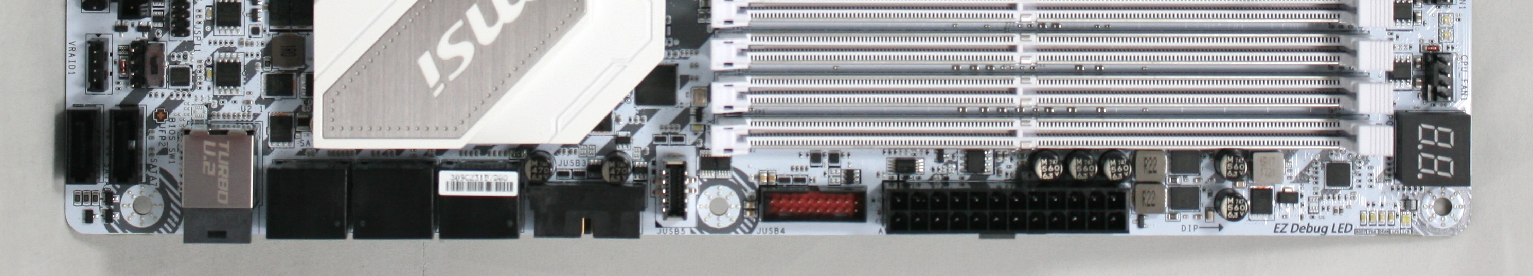
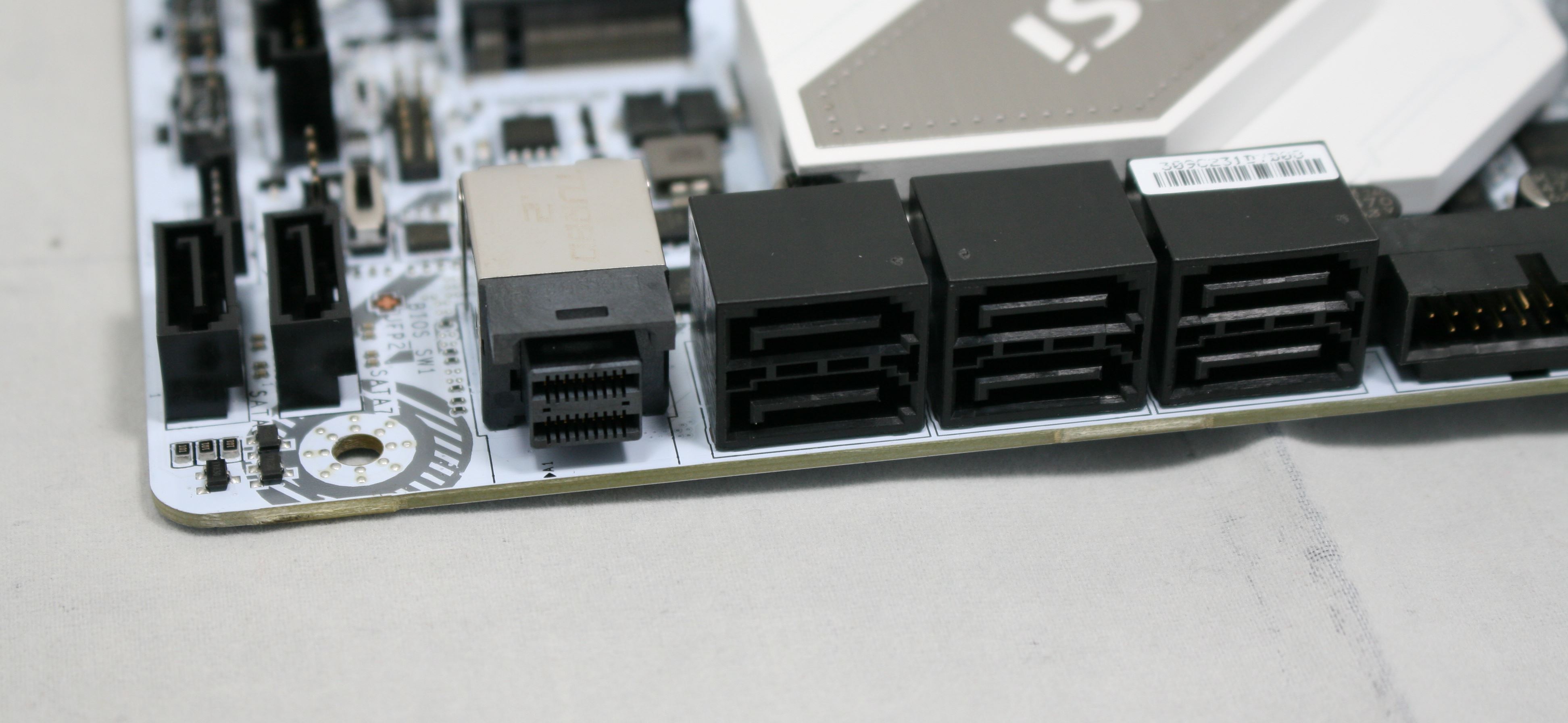
Sitting just below the 24-pin ATX connector is a front panel USB 3.1 (5 Gbps) header and below that the front panel USB 3.1 (10 Gbps) Type-C front panel header provided through an ASMedia 3142 controller.
Six of the eight SATA ports (1-6) are located on the right edge of the board to the right of the PCH heatsink while the other two (7-8) are just to the other side of the U.2 connector and oriented vertically. Be aware some combination of drives will disable SATA ports and/or PCIe slots. When using the U.2 connector, the third PCIe slot will be disabled. When using the first M.2 slot with a SATA device, the first SATA port will be disabled. When a device is in the second M.2 slot, if it is PCIe, then SATA 5-8 are disabled. If it is a SATA device, only SATA 5 is disabled.
The physical orientation of the PCIe slots has three slot spacing between the first and fourth slots to allow for large triple slot cards to fit or double with some breathing room. These two slots are reinforced using MSI's Steel Slot to prevent damage to the PCIe connector from heavy cards, especially during transport. The Tomahawk supports 3-Way SLI and Crossfire multi-GPU configurations. PCIe full-length slots 1, 4, and 6 are CPU connected while slot 3 and the smaller x1 slots in black are fed from the chipset. The CPU connected lanes break down to a maximum of x16, x16, and x8.

Below is a table describing all of the options and breakdowns for the PCIe lanes. How their lanes break down will vary by the CPU installed. In the table below it is broken down with the "@" symbol noting which slots to put the GPUs in for optimal performance. The only device which will affect slot availability will be U.2 devices as it shares bandwidth with the third PCIe slot (x4). The slot configuration is such that there is room for a triple slot video card when running in slots one and four (the two reinforced slots).
| MSI X299 Tomahawk Arctic CPU PCIe Layout |
|||||||
| 44-Lane 1/2-Way |
44-Lane 3-Way |
28-Lane 1/2-Way |
28-Lane 3-Way |
16-Lane 1-Way |
16-Lane 2-Way |
16-Lane 3-Way |
|
| PCIe 1 | @x16 | @x16 | @x16 | @x16 | @x8 | @x8 | @x8 |
| PCIe 4 | @x16 | @x16 | @x8 | @x8 | x4 or x8 | @x8 | @x4 |
| PCIe 6 | x8 | @x8 | x4 | @x4 | x4 or x0 | - | @x4 |
| PCIe 3 - PCH Shares with U.2 |
x4 | x4 | x4 | x4 | x4 | x4 | x4 |
| SLI | Yes | Yes | Yes | 2-Way | - | Yes | No |
| Crossfire | Yes | Yes | Yes | Yes | Yes | Yes | Yes |
Between PCIe slots 1/3 and 5/6, are the two M.2 locations. The top M.2 slot is cooled by an extension of the chipset heatsink. On the bottom of the heatsink, there is a thermal pad which makes contact with the M.2 module in order to cool the drive. This slot holds up to an 80mm module while the second, without a heatsink, supports drives up to 110mm.
To the right of the PCIe slots sit the chipset and chipset heatsink. Below that are the two BIOS chips and a switch for choosing which BIOS to run off of. It is always good to have a second BIOS to fall back on in case of a flashing error, or if it gets corrupted with overclocking. The Tomahawk Arctic has a BIOS Flashback feature which allows flashing the BIOS without a CPU installed. We see the Thunderbolt 3 5-pin AIC connector there as well.
Moving to the bottom left part of the board, we get the audio. The X299 Tomahawk Arctic uses an EMI shielded Realtek ALC1220 codec with Chemi-con audio capacitors as well as gold plating on the plugs to prevent corrosion and oxidation. The motherboard has an isolated audio design with an RGB LED border and separate audio layers for the left and right channels. It offers de-pop protection and has a dedicated headphone amplifier which auto-detects impedance and can be used with up to 600Ω cans.
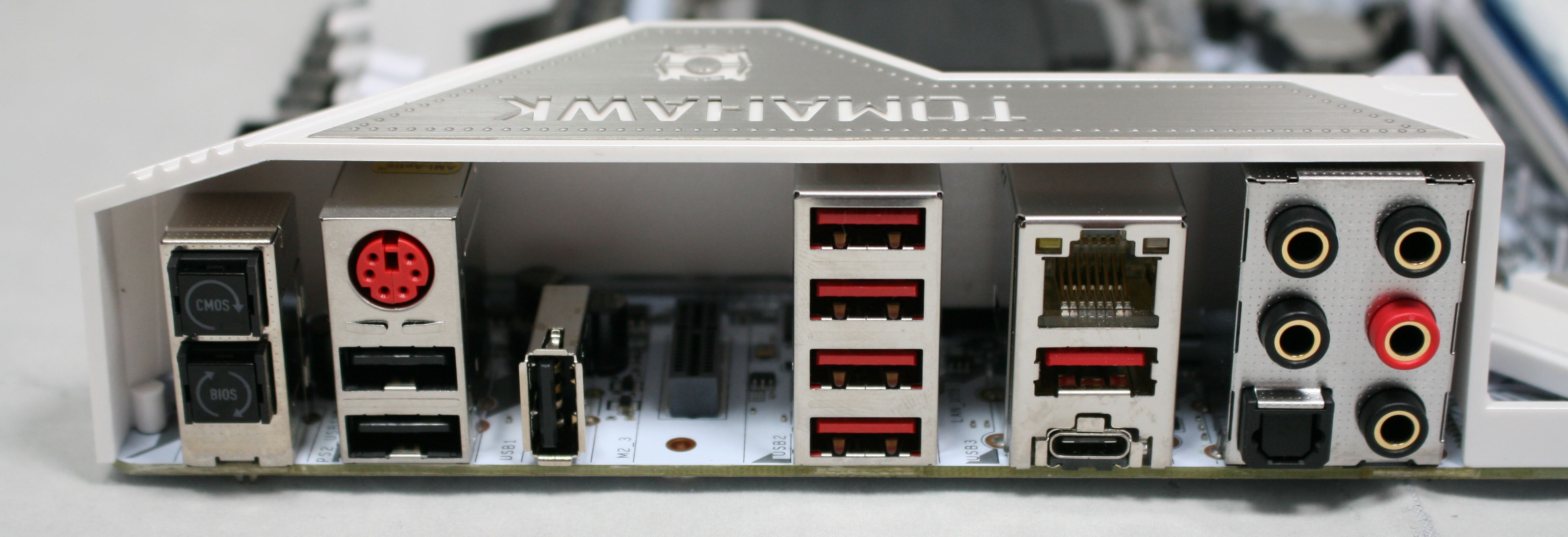
The IO area is pretty standard fare. From left to right we see a Clear CMOS button and BIOS Flashback button, a combination PS/2 port, three USB 2.0 ports (a vertically oriented USB 2.0 port used for BIOS Flashback), four USB 3.1 (5 Gbps) ports, the Intel NIC, USB 3.1 (10 Gbps) Type-A and Type-C ports, and the audio stack which includes optical SPDIF. Those paying attention may notice a gap between the BIOS Flashback port and the USB stack for a Key-E M.2 slot which can be used for a Wi-Fi card.
In The Box
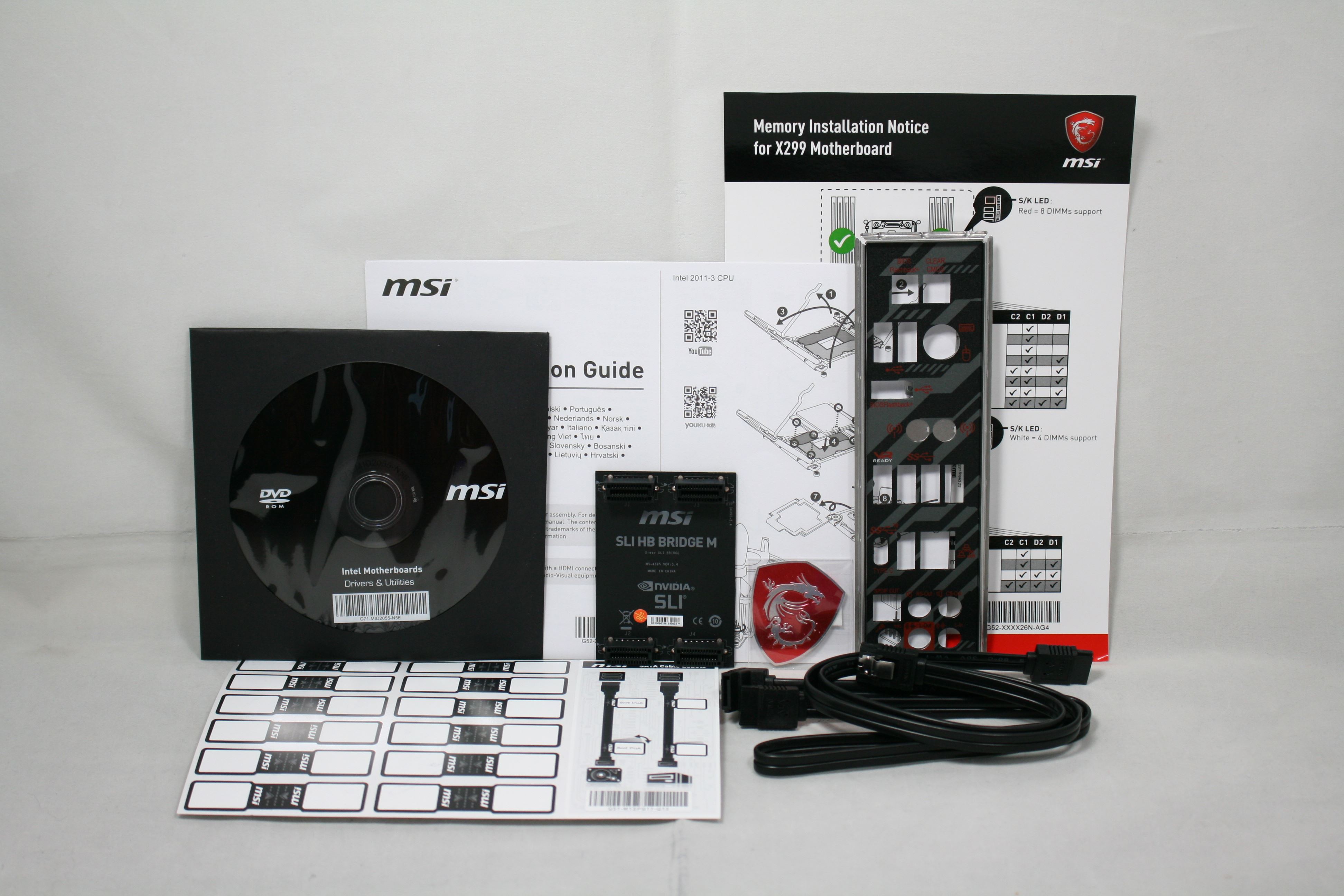
We get the following:
- Quick Installation Guide, User Guide (not pictured)
- Support CD (drivers, utilities, AV software, etc)
- I/O Shield
- Memory Installation Notice, Labels for SATA Cables
- 2 x SATA Cables
- 1 x MSI SLI_HB Bridge_2S Card
- MSI Gaming Badge


21 Comments
View All Comments
prophet001 - Tuesday, November 21, 2017 - link
Anyone delidded?