The Iceberg Thermal IceSLEET G6 Stealth Review: Top-Tier Colossal Tower Cooler
by E. Fylladitakis on October 13, 2022 8:00 AM ESTTesting Methodology
Although the testing of a cooler appears to be a simple task, that could not be much further from the truth. Proper thermal testing cannot be performed with a cooler mounted on a single chip, for multiple reasons. Some of these reasons include the instability of the thermal load and the inability to fully control and or monitor it, as well as the inaccuracy of the chip-integrated sensors. It is also impossible to compare results taken on different chips, let alone entirely different systems, which is a great problem when testing computer coolers, as the hardware changes every several months. Finally, testing a cooler on a typical system prevents the tester from assessing the most vital characteristic of a cooler, its absolute thermal resistance.
The absolute thermal resistance defines the absolute performance of a heatsink by indicating the temperature rise per unit of power, in our case in degrees Celsius per Watt (°C/W). In layman's terms, if the thermal resistance of a heatsink is known, the user can assess the highest possible temperature rise of a chip over ambient by simply multiplying the maximum thermal design power (TDP) rating of the chip with it. Extracting the absolute thermal resistance of a cooler however is no simple task, as the load has to be perfectly even, steady and variable, as the thermal resistance also varies depending on the magnitude of the thermal load. Therefore, even if it would be possible to assess the thermal resistance of a cooler while it is mounted on a working chip, it would not suffice, as a large change of the thermal load can yield much different results.
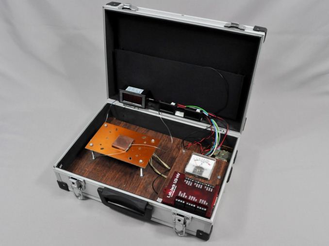
Appropriate thermal testing requires the creation of a proper testing station and the use of laboratory-grade equipment. Therefore, we created a thermal testing platform with a fully controllable thermal energy source that may be used to test any kind of cooler, regardless of its design and or compatibility. The thermal cartridge inside the core of our testing station can have its power adjusted between 60 W and 340 W, in 2 W increments (and it never throttles). Furthermore, monitoring and logging of the testing process via software minimizes the possibility of human errors during testing. A multifunction data acquisition module (DAQ) is responsible for the automatic or the manual control of the testing equipment, the acquisition of the ambient and the in-core temperatures via PT100 sensors, the logging of the test results and the mathematical extraction of performance figures.
Finally, as noise measurements are a bit tricky, their measurement is being performed manually. Fans can have significant variations in speed from their rated values, thus their actual speed during the thermal testing is being recorded via a laser tachometer. The fans (and pumps, when applicable) are being powered via an adjustable, fanless desktop DC power supply and noise measurements are being taken 1 meter away from the cooler, in a straight line ahead from its fan engine. At this point we should also note that the Decibel scale is logarithmic, which means that roughly every 3 dB(A) the sound pressure doubles. Therefore, the difference of sound pressure between 30 dB(A) and 60 dB(A) is not "twice as much" but nearly a thousand times greater. The table below should help you cross-reference our test results with real-life situations.
The noise floor of our recording equipment is 30.2-30.4 dB(A), which represents a medium-sized room without any active noise sources. All of our acoustic testing takes place during night hours, minimizing the possibility of external disruptions.
| <35dB(A) | Virtually inaudible |
| 35-38dB(A) | Very quiet (whisper-slight humming) |
| 38-40dB(A) | Quiet (relatively comfortable - humming) |
| 40-44dB(A) | Normal (humming noise, above comfortable for a large % of users) |
| 44-47dB(A)* | Loud* (strong aerodynamic noise) |
| 47-50dB(A) | Very loud (strong whining noise) |
| 50-54dB(A) | Extremely loud (painfully distracting for the vast majority of users) |
| >54dB(A) | Intolerable for home/office use, special applications only. |
*noise levels above this are not suggested for daily use


22 Comments
View All Comments
meacupla - Thursday, October 13, 2022 - link
That TPC 812 has the vapor chamber on the wrong side of the stack.It should go CPU | CPU heat spreader | vapor chamber | heatpipes. Kind of like how the RTX 4090 heatsink is designed.
Threska - Sunday, October 16, 2022 - link
Expensive, and more important no AM5 version.https://www.microcenter.com/product/635270/icegian...
WildBikerBill - Saturday, November 5, 2022 - link
Meanwhile, MicroCenter is still the seller and selling it with AM5 support here: https://www.amazon.com/IceGiant-ProSiphon-Desktop-...Foeketijn - Tuesday, November 8, 2022 - link
Then don't delid your CPU. The lid is 100% copper, so that'll take care of any unevenly spread out heat output.edzieba - Thursday, October 13, 2022 - link
Can you add a photo of it mounted on a motherboard to the article? Just the cooler on its own makes it almost impossible to judge scale (as cooler baseplates are not a standard size).Harry_Wild - Thursday, October 13, 2022 - link
Exactly what I want only it too high for my case which has 137mm limit on it! 160 mm is to high!
megadirk - Thursday, October 13, 2022 - link
Too bad it only comes with that color option, especially since it's called the "Stealth". At least it's easily removable to paint and not to difficult of an assembly to model and 3d print a replacement.thestryker - Thursday, October 13, 2022 - link
This seems like an interesting cooler, but like most of the high end air coolers there's so much weight. Would love to see something done bracing wise even if it's just some sort of attachment which can screw into the top of the case.Jonny314159 - Friday, October 14, 2022 - link
These results just tell me to keep buying the NH-D15.NeatOman - Friday, October 14, 2022 - link
I think there should be multiple loads they should be tested at. Heat pipes rely on a small amount of liquid in them evaporate (causing it to cool via phase change) and condense to then be wicked back, these evaporative temps can be change by modifying the liquid. This will in turn give you target temperatures that you have to balance with how well your cooling the heat pipes (fins and fans) and the thermal resistance from the heat pipes to the silicon die.Older chips with much larger die would be able to move much more heat into the IHS and it would benefit to set the gas off temperature higher inside the heat pipes. Now with chips so small it would be harder to move so much heat and a lower temperature would IMO help cool the CPU die better.
The next step is what I've seen on GPU's for a long time. Two stage phase change. First is a vapor chamber block sitting directly on the GPU die and then you have heat pipes on top to further move the heat away. It would be amazing to see the Thicc IHS on the Ryzen 7000 series chips be turned into a vapor chamber.
You can see how the new RTX 4090 can suck down just over 600 watts when overclocked yet with a volume of about equivalent to a max size tower CPU cooler it runs surprisingly cool.
DO IT AMD.. DO IT ! would be amazing if someone made IHS replacements that are said vapor chambers :-)