The ASRock X299 Taichi Motherboard Review
by Joe Shields on October 31, 2017 8:00 AM EST- Posted in
- Motherboards
- Intel
- ASRock
- SLI
- CrossFire
- Taichi
- X299
- Skylake-X
- Kaby Lake-X
Visual Inspection
The overall look of the board is similar to the Gaming i9 from the memory slot layout, the PCIe layout, and the overall basic color scheme with a black PCB with gray stenciling. The stenciling on the Taichi, however, looks like planetary gears and is primarily found through PCIe area. The chipset heatsink also follows this cog theme and is shaped like a gear. With its color scheme as it is, the X299 Taichi should fit in with most build themes. If RGB LEDs are your thing, there are a few on the board and are found underneath the chipset heatsink - these are adjusted through the included ASRock RGB LED software. Additionally, there are two 4-pin RGB headers (in white) located at the top right and bottom left of the board. They can handle common 5050 RGB LED strips, under 2M long with a maximum power rating of 3A(12V) according to the manual.
We get five 4-pin fan headers in total, with the two main ones for the CPU cooler flanking the right set of memory slots are two 4-pin headers. The CPU fan connector is able to output a maximum of 1A (12W) while the CPU and Chassis Optional/Water Pump headers can both deliver 1.5A (18W). Two other fan headers are located just below the chipset heatsink; one is labeled a chassis fan the other an optional water pump header. The fifth fan header (chassis) sits inside the left set of memory close to the bottom left of the processor socket. All fan headers are able to auto-detect if a 3-pin or 4-pin device is used and adjust control methods as needed.

The socket area on the Taichi is clean, and uses the same 13-phase power delivery as the Professional Gaming i9, with all of the 12K caps are in the same locations. The heatsink looks like the same chunk of aluminum as well, just styled a bit differently.

The power delivery consists of three Intersil ISL69138 digital PWMs with ISL66176 phase doublers hiding out on the back of the board. These all-digital PWMs are matched with ISL99227B and ISL99227F Smart Power stages. The Taichi uses two Sinopower SM7341EH dual-N channel MOSFETs for the memory. These are different than the Fairchild units used on the Professional Gaming i9. Above the VRM heatsink, slightly off-center to the right, is where the single 8-pin EPS 12V connector is found.

Moving clockwise around the board, to the right of the memory slots we find the 24-pin ATX power. Sitting right below it are two USB3.0 (5Gbps) headers controlled by an ASM1074 controller. Hiding between those two connectors is a pad for a front panel Type-C USB3.1 (10Gbps) header, which the Taichi doesn't have. It is worth noting that below the left-hand memory slots there is an IC pad missing as well - this is where the Aquantia 10 GbE controller was on the Professional Gaming i9 which is not a feature used on the Taichi.
Moving down to the bottom part of the board and starting from left to right the first item to mention is the audio. Hidden under the shroud is a Realtek ALC1220 codec. Amplifier duties are handled by a Texas Instruments NE5532 operational amplifier (up to 600Ω headphones supported) and Nichicon Fine Gold series audio capacitors. EMI shielding is surprisingly non-existent on the Realtek IC itself, but the board does have physical PCB isolation to help minimize interference. The Taichi uses Purity Sound 4 software to shape the 7.1 channel audio to the user's liking.
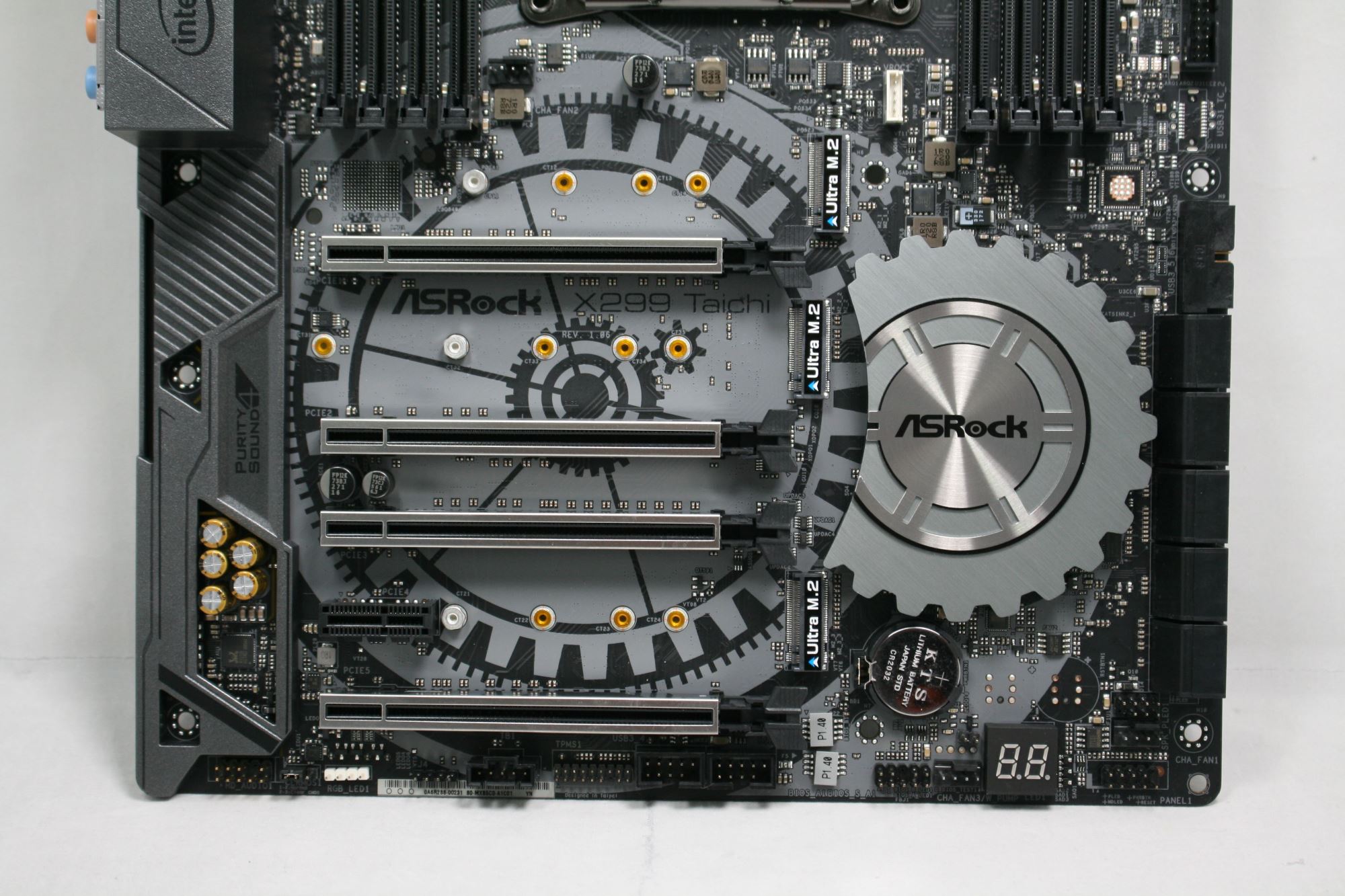
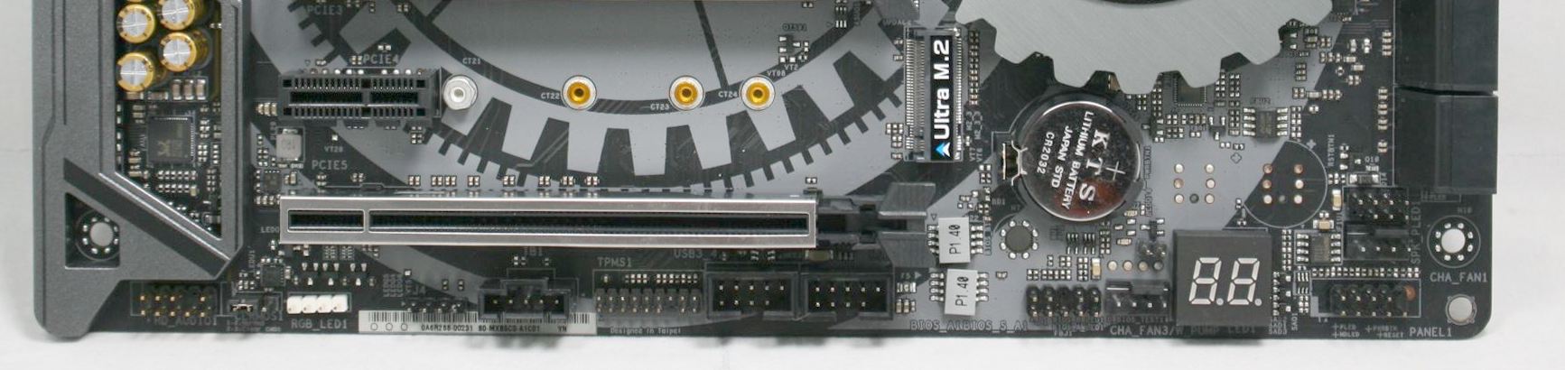
The PCIe lanes are the exact same physical setup as the Gaming i9. There are a total of four full-length x16 PCIe slots (called PCIe 1, 2, 3, and 5 from top to bottom in the manual) and also has one PCIe slot (designated as PCIe 4). The x1 slot is fed from the chipset while all the full-length slots are handled by the processor.
When using multiple GPUs, ASRock says to use PCIe 1, PCIe 3 and PCIe 5 (the first, third, and fifth slots). This configuration gives the first slot room for large video cards and plenty of room for that top card that typically runs the hottest in a multi-GPU setup. See spec table below as well as well as details from the manual on 44 and 28 lane CPU splits. The last full-length slot (PCIe 5) receives x8 lanes from the first PCIe slot when in use
| ASRock X299 Taichi PCIe Layout | ||||||
| 44-Lane 1/2-Way |
44-Lane 3-Way |
28-Lane 1/2-Way |
28-Lane 3-Way |
16-Lane 1-Way |
16-Lane 2-Way |
|
| PCIe 1 | x16 | x8 | x16 | x8 | x16 or x8 | x8 |
| PCIe 2 | x8 | x8 | - | - | - | - |
| PCIe 3 | x16 | x16 | x8 | x8 | - | x4 |
| PCIe 5 | - | x8 | - | x8 | - | - |
| 1st M.2 | x4 | x4 | x4 | x4 | None or x4 | x4 |
| SLI | Yes | Yes | Yes | Yes | No | No |
| Crossfire | Yes | Yes | Yes | Yes | No | Yes |
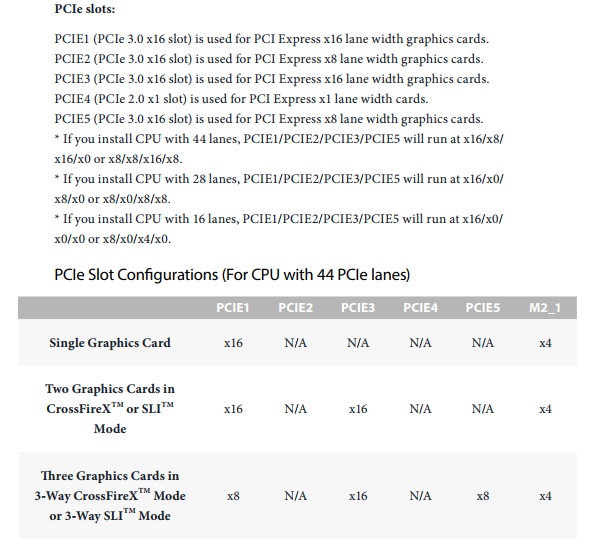
As with most X299 motherboards, where exactly the PCIe lanes go when things get populated is sometimes a hair removing exercise. The table above has all the combinations, which show two odd combinations. Firstly, the top PCIe 1 slot and bottom PCIe 5 slot share lanes when using a 44 or 28-lane CPU (normally shared PCIe slots are closer together), and secondly is the first M.2 slot support on a 16-lane processor. Because this slot is powered by the processor, users will have to give up at least 8 lanes when a single GPU is used to power it, and lose SLI compatibility when two GPUs are being used. ASRock states that even if a user has two GPUs and uses the non-CPU based M.2 slots, the board is still not certified for SLI-use when Kaby Lake-X processors are in play.
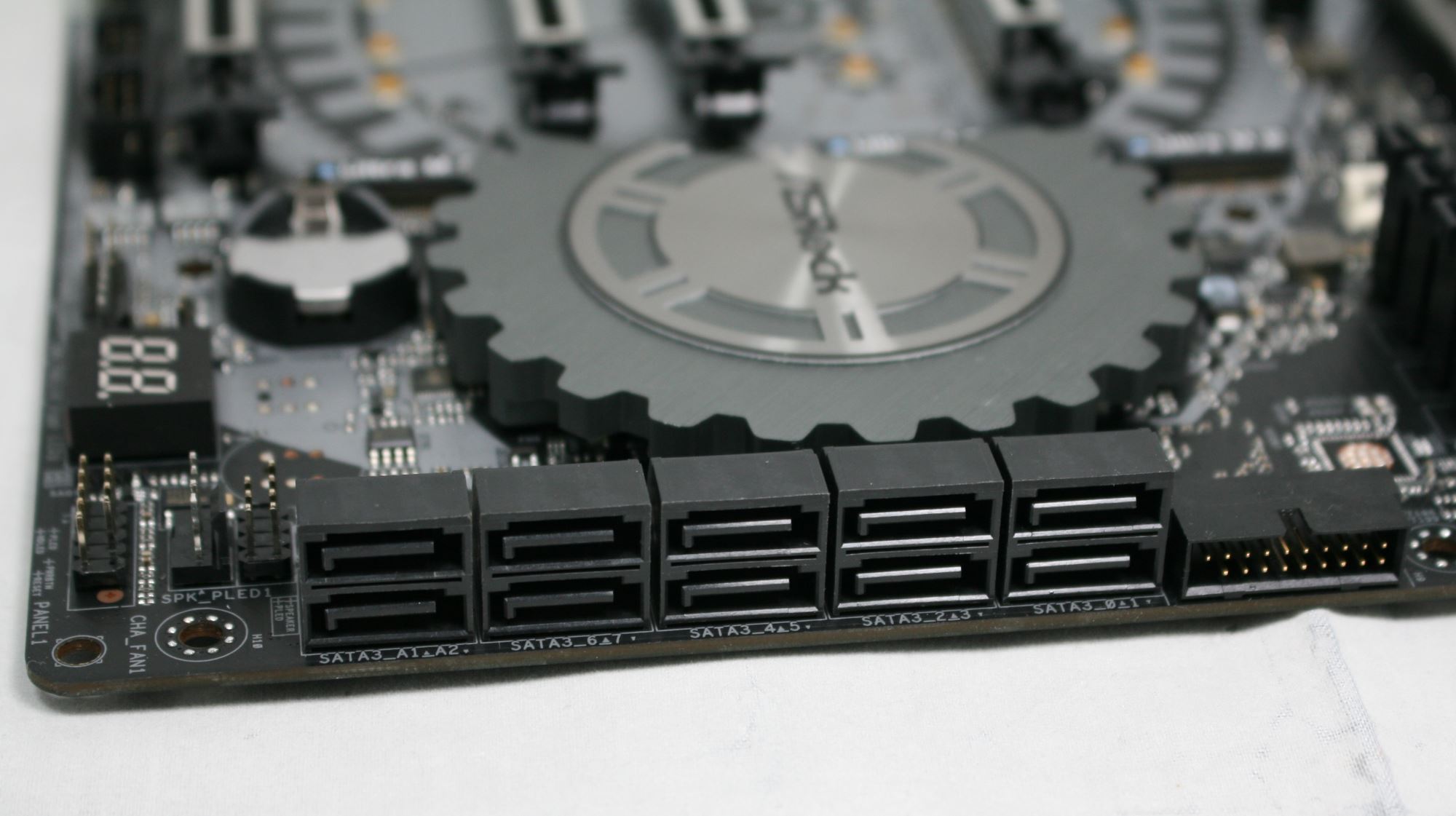
For storage, there are 10 SATA ports and three M.2 slots. As mentioned, the first M.2 slot is powered by the processor, while the other two are from the chipset. The middle slot can hold up to a 110 mm device, while the top and bottom slots support up to 80 mm devices.
All the SATA ports on the board are located in a strip on the bottom right corner. The ASMedia 1061 driven ports (2) are on the left, labeled A1 and A2, while the eight ports from the chipset are to the right, labeled SATA 0-7. When using SATA based M.2 drives, those slots share bandwidth and disable some SATA ports. For example:
- M2_1 is occupied by a SATA-type M.2 device, SATA 3_1 will be disabled.
- M2_2 is occupied by a SATA-type M.2 device, SATA 3_0 will be disabled.
- M2_3 is occupied by a SATA-type M.2 device, SATA 3_7 will be disabled.
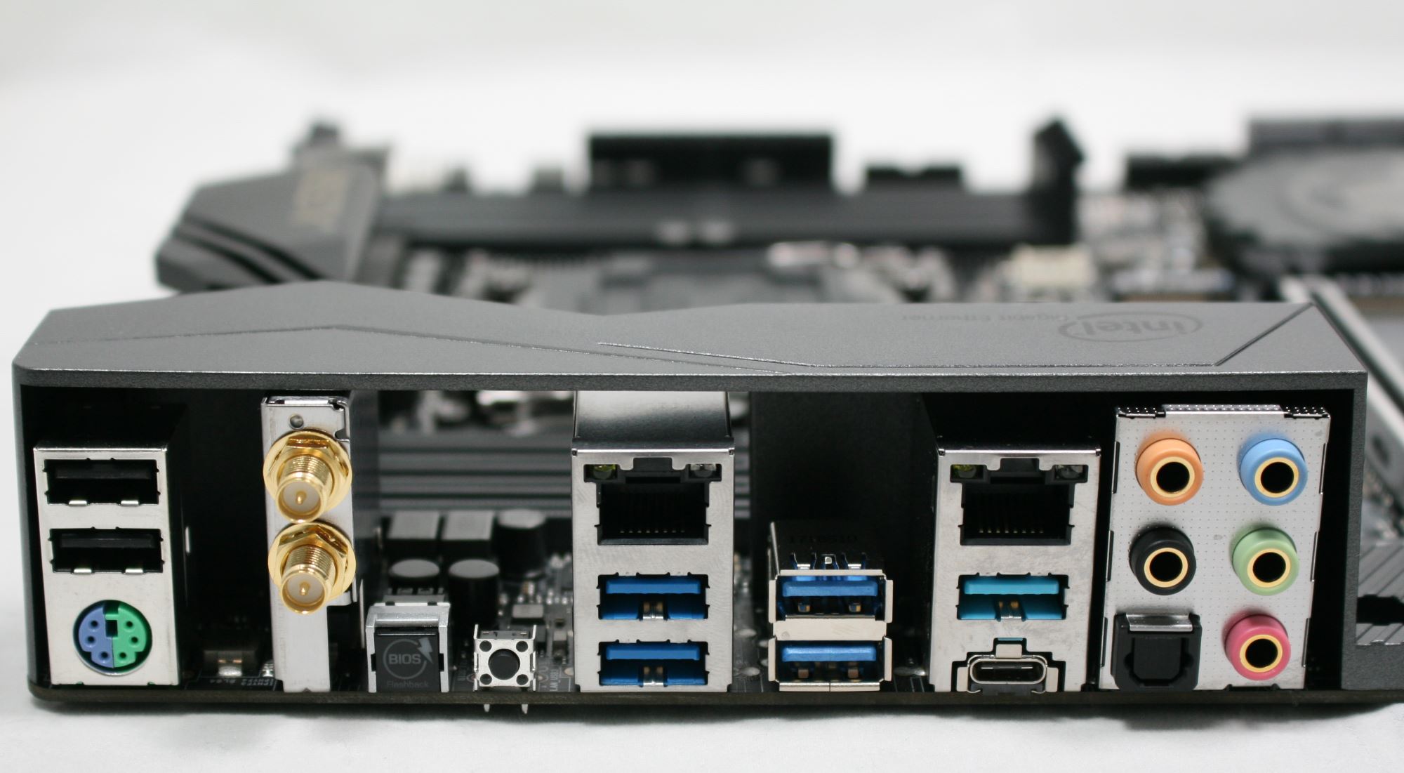
The I/O area is fairly standard. From left to right we see a combination PS/2 port, below two USB2.0 ports. Next is the Intel AC3168 Wi-Fi module, as well as the BIOS Flashback button and CMOS reset button. To the right is one of the two Intel LANs and four USB 3.1 (5 Gbps) ports. The second Intel LAN port sits above the ASMedia 3142 driven USB 3.1 (10 Gbps) Type-A and Type-C ports. Last is a standard audio stack with Optical SPDIF.


In The Box
We get the following:
- Quick Installation Guide, Support CD (drivers, Utilities, AV Software, etc), I/O Shield
- 4 x SATA Data Cables
- 1 x ASRock SLI_HB Bridge_2S Card
- 1 x ASRock 3-Way SLI-2S1S Bridge Card
- 2 x ASRock WiFi 2.4/2.5GHz Antennas
- 3 x screws for Ultra M.2 Sockets
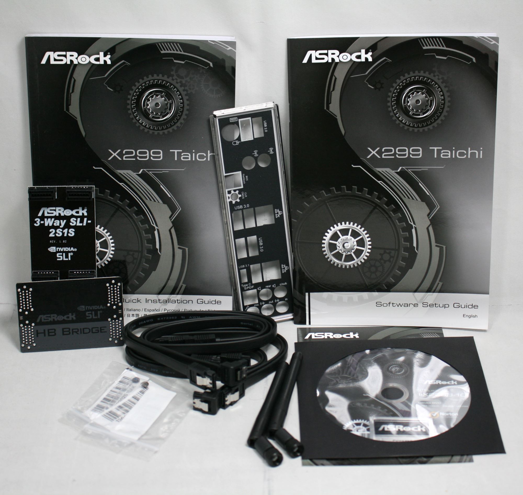
The included accessories are sparse but the package contains enough to get started. Long gone are the days where we see eight SATA cables in most accessories packages as M.2, both SATA and PCIe based, are seemingly making good headway in the market. It includes a hard 3-Way SLI bridge and 2-Way HB bridge. Screws for the M.2 slots are also included as well as the antenna to connect to the Wi-Fi to aid in better signal reception.


17 Comments
View All Comments
UltraWide - Tuesday, October 31, 2017 - link
I love the PCIe lane chart, so simple and effective!hansmuff - Tuesday, October 31, 2017 - link
"Gaming is still a primary use on most motherboards and though 'Gaming' isn't in the Taichi's name, it keeps the same PCIe slot spacing, configuration, and slot protection as the Gaming i9, making the setup for multi-GPU configurations."I think you may have skipped a word :)
hansmuff - Tuesday, October 31, 2017 - link
And I replied to the wrong post. Oh well!Joe Shields - Wednesday, November 1, 2017 - link
Updated Yesterday. Good catch! Thank you!peevee - Tuesday, October 31, 2017 - link
"10 SATA ports"Why?
peterfares - Wednesday, November 1, 2017 - link
Yeah not sure why they're bothering with the controller to add the two extra.I guess some people need that many. Must want a lot of hard drives but not have them be externally connected through a NAS or other storage server.
jabber - Wednesday, November 1, 2017 - link
There will always be people that want to run the wrong hardware for the wrong job. Let them get on with it I say.ikjadoon - Tuesday, October 31, 2017 - link
I think this may have been left in body style instead of subheader style, on the overclocking page:Overclocking Results
Joe Shields - Tuesday, October 31, 2017 - link
Updated where needed. Thanks!Qasar - Tuesday, October 31, 2017 - link
so even with a 44 lane cpu, PCIe slot 5 has no connection ?? example.. vid card in Slot 1, sound card in slot 4, the x4 slot, so where would say a raid card go ?? slot 3 or slot 5?????