The ASUS ROG Strix X299-XE Gaming Motherboard Review: Strix Refined
by Joe Shields on December 11, 2017 8:00 AM EST- Posted in
- Motherboards
- Asus
- X299
- Skylake-X
- Kaby Lake-X
ASUS Strix X299-XE Gaming Visual Inspection
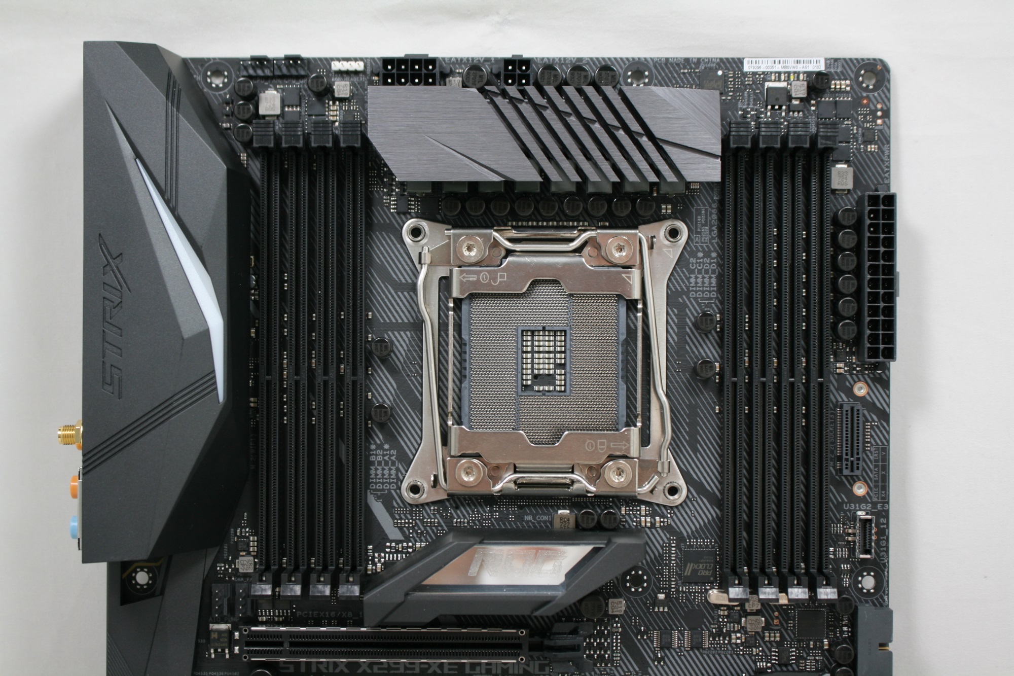
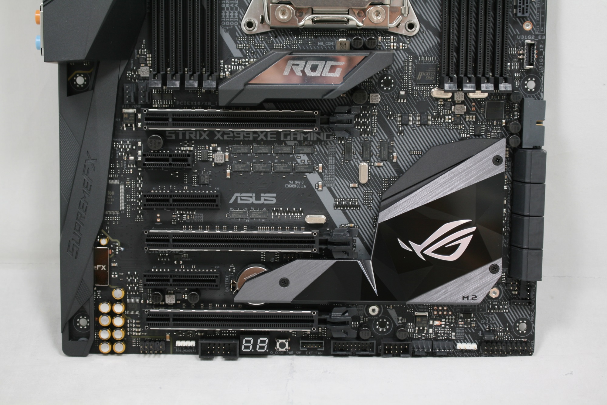
The ROG Strix X299-XE Gaming has a fairly simple look to it, with a black PCB, DRAM slots, and PCIe slots. For onboard styling, ASUS uses a pattern of lines going from the PCH heatsink through to the socket area on the PCB, with angled heatsinks with consistent angled grooving. It's clear that ASUS is using specific angles in its styling to match the look across the whole board.
A shroud covers the back panel IO and audio section, which is also where one of the two onboard RGB LEDs are located. The second is located in the middle of the board between the socket and first full-length PCIe slot. Additional RGB LEDs can be added through the board's two onboard headers. For the central heatsink, users are able to 3D print and customize what that area displays. The chipset heatsink is oddly shaped as it has a part sticking out which is designed to cool an M.2 device underneath. On the bottom of the board is where the two-digit debug display is, as well as a simple power button.
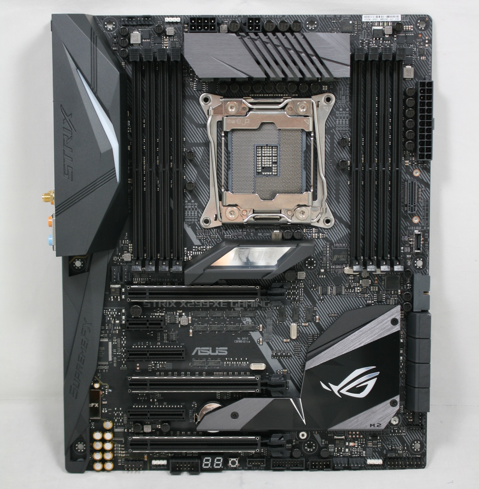
There are 7 fan headers on the board, with some also supporting high-power water-cooling pumps. The first two CPU fan headers are at the top of the board above the left DRAM slots. On the bottom, below the chipset heatsink, are two more (the W PUMP+ and CHA FAN2 headers). Another is just below the SATA ports and is for an M.2 FAN. The last two are nestled between the bottom of the left DRAM slots and above the first full-length PCIe slot, and are designated for the AIO PUMP and CHA FAN1 headers. All the onboard headers support auto-detection of PWM or DC controlled fans.
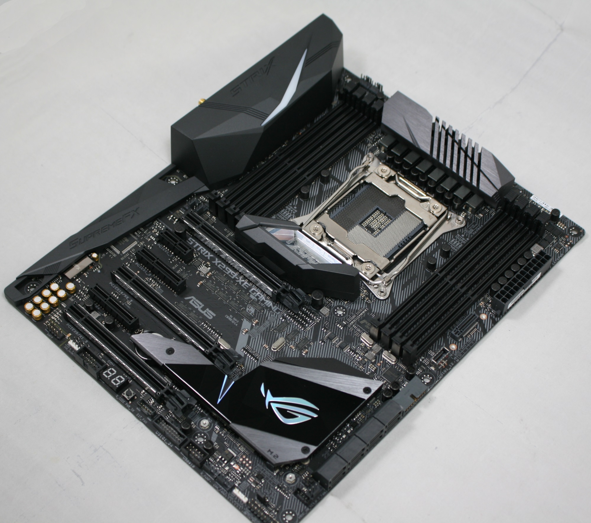
The ASUS ROG Strix X299-XE Gaming uses the same VRM as the non-XE version, only the heatsink is larger, includes a bracket, and a 40x40mm fan to mount on top for additional cooling. The power delivery is driven by ASUS' 8 Phase Digi+ VRM controller (Infineon IR35201) and controls seven 60A Infineon IR3555M MOSFETs along with one smaller Texas Instruments CSD97374Q4M NexFET. Getting power to the VRM is a required 8-pin EPS 12V connector as well as an optional 4-pin EPS 12V.
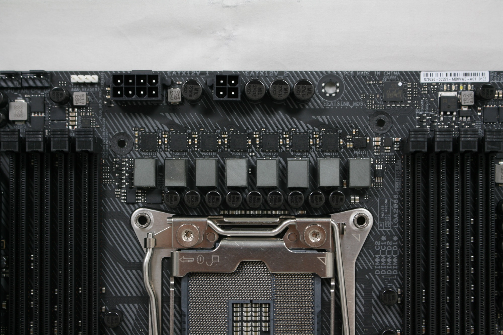
The DRAM slots on the ROG Strix X299-XE Gaming are not reinforced and use a one latch system to lock the sticks in place. Memory compatibility is up to DDR4-4133 for both Skylake-X (quad-channel) processors and Kaby Lake-X (dual-channel), with support up to 128 GB and 64 GB respectively. In the upper right-hand corner is the Q-LED display to show users where in the POST process they happen to be. These, along with the two-digit debug display on the bottom of the board are both useful tools for troubleshooting POST issues.
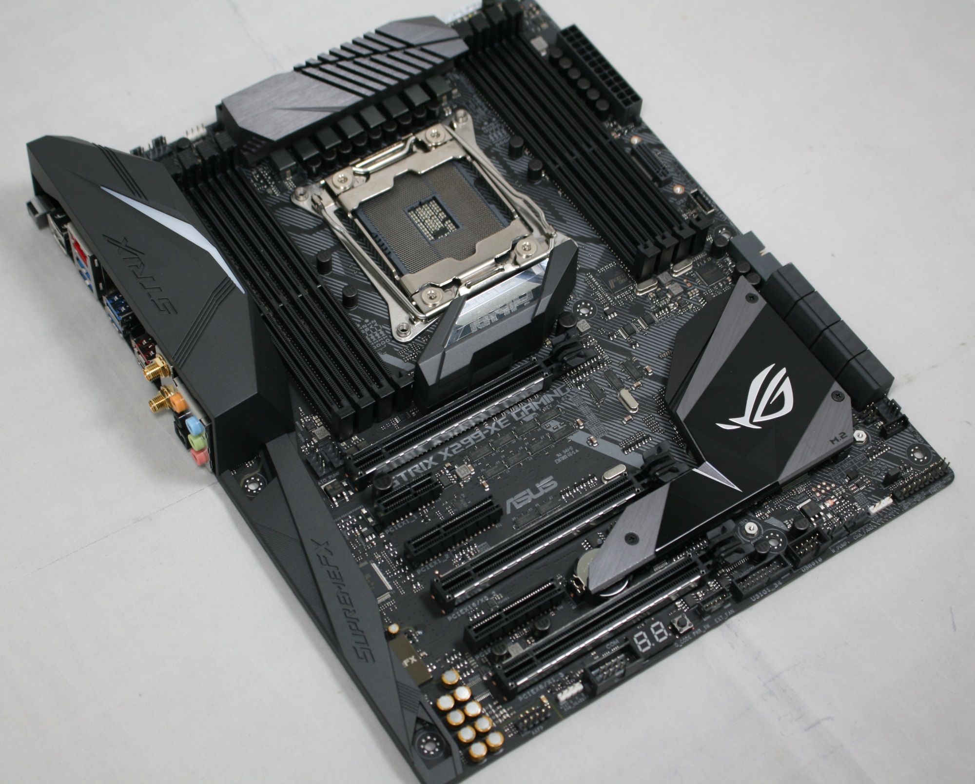
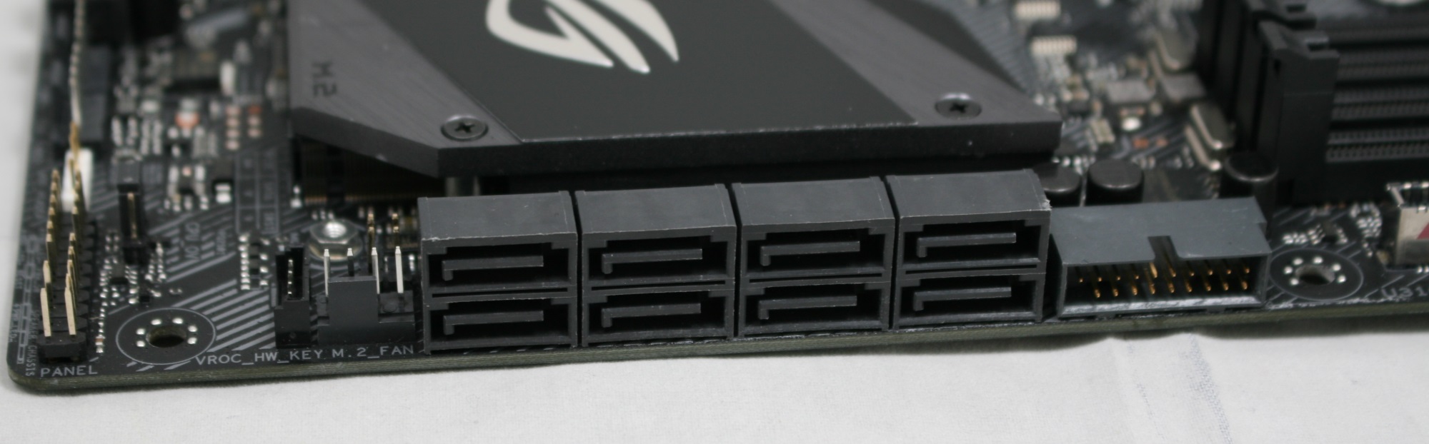
From top to bottom on the right-hand side of the board, the first item is the 24-pin ATX connector for board power. Next to it is the vertical M.2 slot, as well as the front panel USB 3.1 (10 Gbps) header. Next is a front panel USB3.0 header, the eight SATA ports, and a fan header.

All eight chipset connected SATA ports are located next to each other in the bottom right-hand corner.
There is a slew of connectivity on the bottom part of the board (image below). On the left we see the Japanese Nichicon audio capacitors in a yellow color, while to the right of it is the front panel audio connector. To the right of that in white is the first RGB header. followed by a serial COM port header. Then we have the two-digit debug and a power switch. The 5 pin fan extension header is to the right of it along with more front panel USB headers and fan headers. Last is the front panel headers in the bottom right-hand corner.
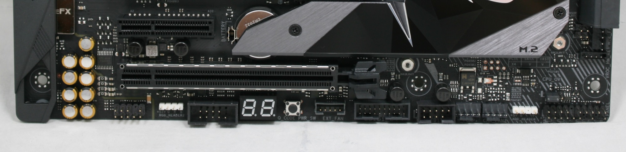
For PCIe, the ROG Strix X299-XE Gaming comes equipped with six PCIe slots. The three full-length slots are connected to the CPU, as well as being steel reinforced, and are used primarily for video cards. The smaller slots are an x1 and two x4 slots (the first runs at 1x) powered by the chipset for add-in cards.
Below is a simplified list of how the PCIe slots will work with each family of CPUs (talking PCIe lanes) when multiple cards are used (the "@" symbol is used to show slot preference for the configuration):
| ASUS ROG Strix X299-XE CPU PCIe Layout | ||||||
| 44-Lane 1/2-Way |
44-Lane 3-Way |
28-Lane 1/2-Way |
28-Lane 3-Way |
16-Lane 1-Way |
16-Lane 2-Way |
|
| PCIe 1 | @x16 | x16 | @x16 | x16 | @x16 | @x8 |
| PCIe 4 | @x16 | x16 | @x8 | x8 | - | @x8 |
| PCIe 6 | x8 | x8 | x1 | x1 | x1 | x1 |
| SLI | Yes | Yes | Yes | No | - | Yes |
| Crossfire | Yes | Yes | Yes | No | Yes | Yes |
Surprisingly the third slot is listed as an x1 slot for any CPU below 44 lanes. Normally we would expect to see an x8/x8/x8 configuration for a 28-lane CPU in 3-way, however it seems that the layout this way makes more sense on this setup? We're not quite sure what the idea was here - the only viable explanation is that perhaps ASUS wants to make sure the first GPU is always at x16.
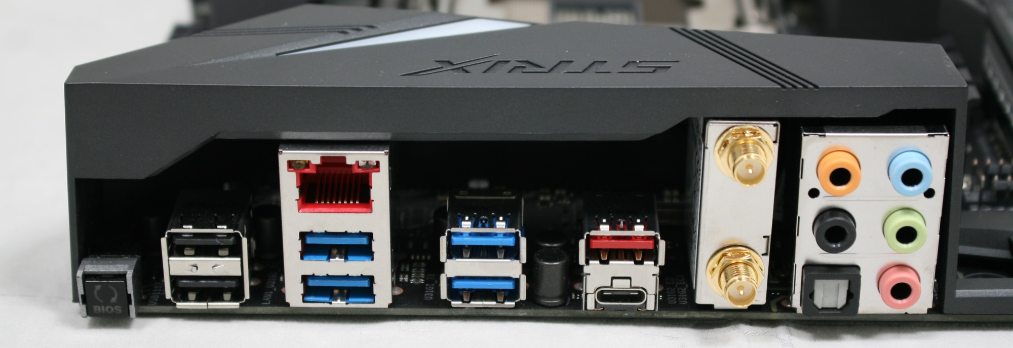
The back IO panel has a BIOS Flashback button, two USB 2.0 ports, the Intel NIC and four USB 3.0 headers. We also see USB 3.1 (10 Gbps) Type-A and Type-C ports in red next to the Intel Wi-Fi unit, and 5 jack audio stack with SPDIF out.


In the Box
Our included accessories fell a bit short of what the website says is included, but this is due to it being a board sent from ASUS. Retail boards will come with everything listed below
We get the following:
- Vertical M.2 bracket set
- 4 x SATA 6Gb/s cables
- M.2 screw package
- Support DVD and Strix Door Hanger
- ASUS 2T2R dual band Wi-Fi antennas
- MOS Cooling kit (fan bracket and 40x40mm fan)
- ROG addressable LED strip
- 2-Way SLI HB Support bridge
- Q-Connector
- 10-in-1 ROG cable label
- M.2 screw kit (long screw and mount)
- Thermal sensor
- Cable ties / Fan labels
- Extension cable for RGB and Addressable lED
- 3D printing mount package
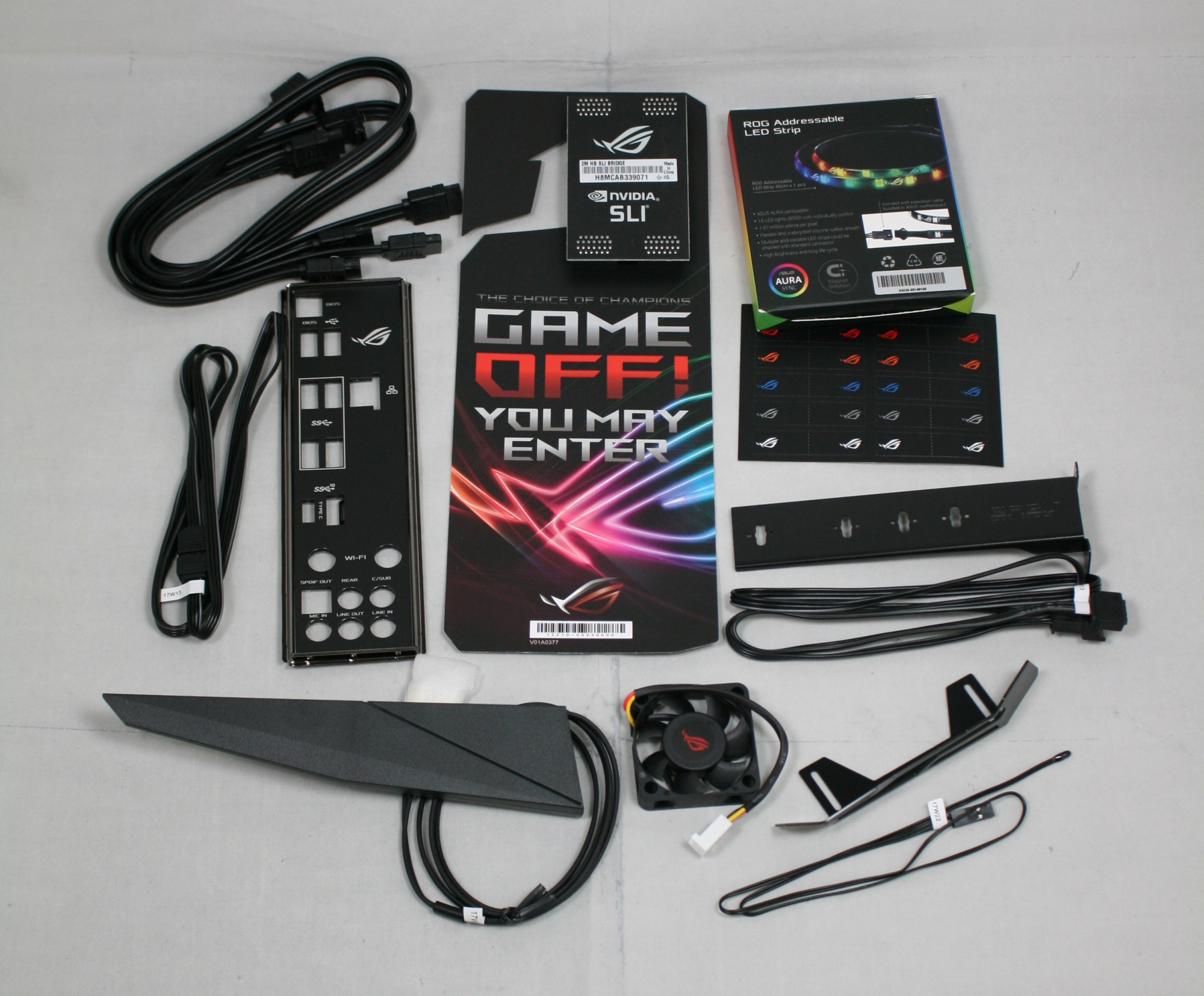
This is a substantial kit for a gaming product, with the optional fan at least being optional. The bundled LED strip is an interesting addition too, moreso than we get with other gaming boards.


27 Comments
View All Comments
MrPoletski - Monday, December 11, 2017 - link
I can totally see ten of thousands of dollars being spent on this board and a corresponding PC of worthwhile power so the owner can play master of orion 2, nes emulators and minecraft. I know, I'm one of those nobs.peevee - Monday, December 11, 2017 - link
Somebody has to seriously grow up instead of wasting $400 for a gaming MB (or a few thou for a gaming computer).ddrіver - Monday, December 11, 2017 - link
"ten of thousands of dollars"? Sounds a bit excessive given that 1 (or 2, where possible) of the most expensive components available still doesn't really get you to $10K. Unless you're buying by sorting for the most expensive anything and taking as many as you can fit in a case.Next thing you're going to brag you pay a guy to comment for you.
DanNeely - Monday, December 11, 2017 - link
" The smaller slots are an x1 and two x4 slots (the first runs at 1x) powered by the chipset for add-in cards. "This seems backwards since the first x4 is always free to put a card in while the second is blocked by the 2nd GPU.
Joe Shields - Monday, December 11, 2017 - link
Hey Dan, I don't blame you for thinking this way. However, from the specifications it says this...:1. PCIEX4_1 max. at x1 mode
Which is the same for all 44/28/16 lane CPUs.
DanNeely - Monday, December 11, 2017 - link
ok. Just wanted to confirm it was a screwy design on Asus's part, not a transcription error.SanX - Monday, December 11, 2017 - link
Where the hell are dual CPU mobos? Intel and AMD don't like to sell more chips?Dr. Swag - Monday, December 11, 2017 - link
Intel has never sold non Xeon products that can be put in dual CPU mobos.PeachNCream - Monday, December 11, 2017 - link
Google says there were dual Pentium, Pentium Pro, Pentium II, Pentium III, and so forth motherboards around so Intel has sold non-Xeon products for dual socket/slot motherboards.DanNeely - Monday, December 11, 2017 - link
With the exception of the P3 all of those predated the Xeon branding. Dual socket P3 was presumably transitional in their rebranding.For modern chips, on the Intel side mainstream parts have neither the on die hardware, nor chip socket support for multi-socket setups because doing so would inflate the costs of the 99.9% of systems that are single socket.
I'm less sure of the situation with AMD. I suspect that due to the level of die sharing they're doing between TR and Epyc that TR cpu dies themselves have the hardware needed to talk to a second CPU socket. However I'm skeptical that they've also paid extra for a larger/more complex socket on mainstream TR parts. It'd raise costs for the 99.9% of uni-socket systems and cut into sales of their more profitable Epyc line.
More generally multi-core CPUs have been heavily eroding the market for multi-socket chips over the last 15 years. They require more complex boards, more complex CPUs, in many cases (ie any that need threads on different sockets to talk to each other) they also require additional programming work to perform at their maximum capacity (AMD has a NUMA hit for new multi die but single socket chips, however its worse for their dual socket ones). All of that means that almost any time you can get a single socket system with a suitable performance level it will be more cost effective than a similar dual (never mind quad or 8way) socket system. With dozens of cores available on Intel and AMD's current high end platforms small core count dual socket systems rarely make sense outside of cases where you need huge amounts of ram and don't really care about CPU performance.