Gigabyte GA-Z77MX-D3H Review – Z77 and MicroATX
by Ian Cutress on May 24, 2012 3:00 PM EST- Posted in
- Motherboards
- Gigabyte
- Z77
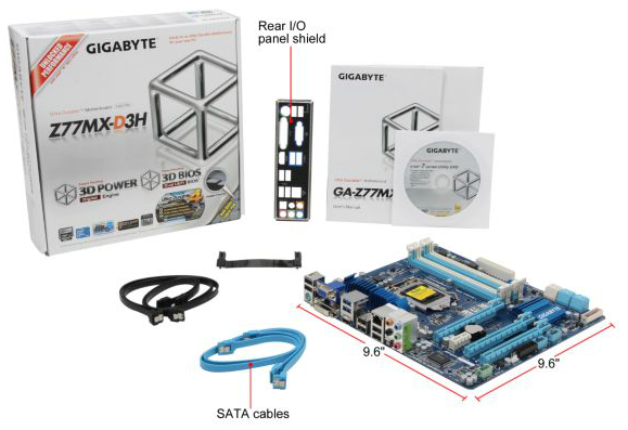
Gigabyte GA-Z77MX-D3H In The Box
Gigabyte rarely produces a shock when it comes to accessories in the box. More often than not they leave it up to the user to source their own additional components, thereby not limiting them (or charging them) for a series of additional controllers they do not want. On the plus side, this helps Gigabyte reach perhaps a lower price point than other manufacturers. On the downside, some users would like an all-in-one motherboard that caters for eventualities. Inside the Z77MX-D3H, we have:
IO Shield
User Manual
Driver CD
Four SATA cables
SLI Bridge
As expected, for $135 all-in the Gigabyte package does not exactly pack a punch for additions. Perhaps we may expect more in our future reviews of the Sniper motherboards?
Voltage Readings
After my first publication of OCCT voltage readings, a few readers responded with a more in-depth reasoning behind some of the results we were seeing. With this in mind, I would like to re-describe what we are doing with this test, and how it comes about.
Much of what an enthusiast overclocker does is monitor CPU temperature and voltage. Whatever settings a user places in the BIOS or OS is at the mercy of the motherboard - in terms of actually setting the values and reporting the values back. As an enthusiast, we have to rely on what readings we get back, and hope that motherboard manufacturers are being honest with their readings.
Take CPU voltage. What we as a user see in CPU-Z or OCCT is a time-averaged value that hides voltage ripple (if any) for power delivery. It is very easy for a motherboard manufacturer to hide this value, or to disregard slight deviations and report a constant value to the user. The CPU voltage reading can be taken at a variety of places on the power plane, which can vary between motherboards and manufacturers, meaning that each reading is essentially not comparable with the other. Nevertheless, as an enthusiast, we will constantly compare value A with value B.
Whether or not I can achieve 4.7 GHz with 1.175 volts on a particular board is inconsequential - your motherboard may perhaps produce the same result with a reading at 1.200 volts. The only way to test the actual value is with consistent methodology is via an oscilloscope connected to similar points on each board. This may sound like taking an OCCT reading is therefore redundant.
However, motherboards have settings relating to load line calibration. As load is applied to the CPU, the voltage across the processor decreases (VDroop). Load Line calibration essentially attempts to control this level of droop, by increasing voltage when voltage drops are detected away from a fixed value. Manufacturers have different ideas on how to modify LLC with respect to load, or whether the level of modification should be controlled by the user. Some manufacturers offer the option at a variety of levels, such that overclockers can be sure of the applied setting (even if it increases peak voltage, as explained by AnandTech in 2007).
By doing a full load OCCT test, we are essentially determining both how aggressive the motherboard is reporting the CPU voltage under load and how aggressive load line calibration is performing (from the point of view of the user without an oscilloscope or DVM). If someone has one of the motherboards we have tested and you have a different one, variations in load voltage should describe the offset you may require for overclock comparisons.
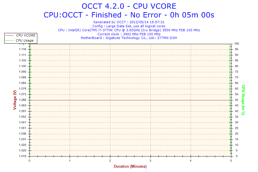
Last time we reviewed a Gigabyte Z77 board, the Z77X-UD3H, we were given a straight line for the voltage in our OCCT test as well. Given the correlation between this test and previous results, it looked 'normal'. That was until I performed some overclocking and used the auto-overclock features. On every change of the CPU voltage, the operating system software would constantly read the same 1.068 volts value. Even if the CPU was set at 1.200 volts, I would still get the 1.068 volts reading (even at load). This means that Gigabyte are artificially putting in a layer between the CPU and the OS and manipulating the results as it passes through to the OS. While this is nothing new (often used for monitoring), the fact that Gigabyte have kept it a fixed value confuses me. As an overclocker, I perhaps cannot see what the real voltage being applied to the CPU is unless I break out a DVM. It is also slightly devious to users who use the voltage value as a marker in reducing power usage. I hope that this will be changed in a future BIOS, but whether this change was malicious or not, it does raise questions as to what else Gigabyte may be changing from real values on the board to reported values.
Overclocking
Note: Ivy Bridge does not overclock like Sandy Bridge. For a detailed report on the effect of voltage on Ivy Bridge (and thus temperatures and power draw), please read Undervolting and Overclocking on Ivy Bridge.
Auto overclock options come purely as part of EasyTune6 software in the operating system. Gigabyte offers three levels of overclock, which essentially apply an array of preset values to the BIOS and reboot the system. Also in ET6 is an 'Auto Tuning' option, which actively applies a stress test on the system and then boosts the CPU speed based on thermal readings and stability. Manual overclocks can be performed in ET6, though for best results a user should head to the BIOS in advanced mode, and navigate through various menus to set speeds and voltages.
Automatic Overclock: In ET6, each of the auto overclock options were tested:
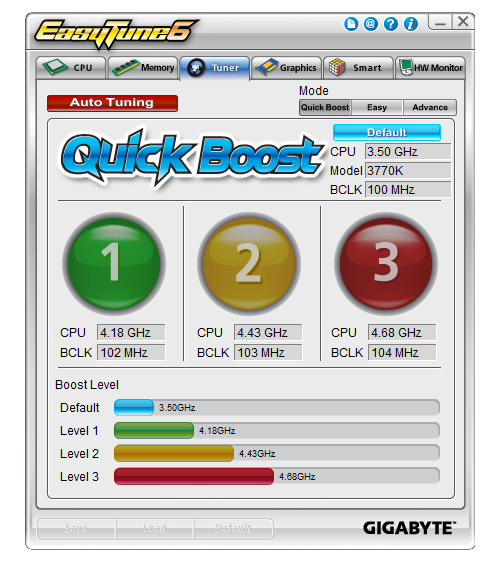
Level 1 sets the CPU at 102 MHz and 41x multiplier, giving 4.18 GHz total. At this setting, the memory was also adjusted to DDR3-2266 9-11-11-29 (compared to DDR3-2400 9-11-11-31 for XMP). At this level, with 100% load, PovRay reached a peak temperature of 83ºC and so did OCCT. The voltage reading from the CPU still showed stock 1.056-1.068 volts, however the temperatures suggest that something closer to 1.175 volts was being applied.
Level 2 sets the CPU at 103 MHz and 43x multiplier, giving 4.44 GHz total. Memory was also adjusted similar to Level 1. At this level, with 100% load, PovRay reached a peak temperature of 87ºC and OCCT gave a peak temperature of 86ºC. This also reiterates a suggested voltage reading of around 1.175V.
Level 3 sets the CPU at 104 MHz and 45x multiplier, giving 4.68 GHz total. At this level, the CPU reached 97ºC peak temperature for PovRay and 100ºC for OCCT. The board would automatically reduce the CPU multiplier to 35x when the CPU was above 97ºC.
The auto tuning setting rebooted the system and then gave a full screen image indicating that overclock testing was taking place. The system initially booted into Auto overclock Level 2, and raised the multiplier slowly while performing stability tests. The program crashed when it reached 48x (at 103 MHz, giving 4944 MHz), and then the system rebooted back to Level 2 setting with no other modification.
Manual Overclock: As with our other Z77 manual overclock testing, here we raise the multiplier slowly and find the minimum voltage at which the CPU successfully passes a run of PovRay and OCCT. While this may not be the most thorough of stability tests, it provides a suitable benchmark to aim for while balancing time taken to test the motherboard. For the Gigabyte Z77MX-UD3H, we implemented an LLC setting of Extreme to ensure stability.
We start at 45x multiplier at 1.100 volts, which gives 69ºC peak temperature during PovRay and 72ºC during OCCT.
At the 46x multiplier, this was stable at a minimum of 1.125 volts, giving 75ºC peak temperature during PovRay and 77ºC during OCCT.
At the 47x multiplier, this was stable at a minimum of 1.200 volts, giving 80ºC peak temperature during PovRay and 84ºC during OCCT.
At the 48x multiplier, the system was not stable even at 1.300 volts, giving 95ºC+ during our testing.
One other point to note is with the F10 BIOS. This BIOS was particularly unstable if the voltage was too low for the CPU clock. This required that after each bad setting that I applied I had to short the ClearCMOS header and then input all the settings again. The BIOS was only partially stable even if the settings were stable in the OS. This is indicative of the way Gigabyte handles overclock settings - the Gigabyte board will apply all BIOS settings immediately at the start of POST, while some other manufacturers only apply overclock settings at the end of the POST to ensure stability in the BIOS. It would perhaps be beneficial for Gigabyte to go down this route, unless the issue is inherently with the BIOS itself.


25 Comments
View All Comments
Soulkeeper - Thursday, May 24, 2012 - link
I like gigabyte, nice review.However, those temperatures for the IB overclock remind me of prescott for some reason.
Night201 - Thursday, May 24, 2012 - link
Works great. Running it with an Ivy Bridge i5-3450 with 8GB RAM and an older 8800gt GPU.Iketh - Thursday, May 24, 2012 - link
Aren't those asrock computation results interesting. The board requires the least volts for your stress tests, yet it appears this is because the board isn't allowing the CPU to stretch its legs.zero2dash - Thursday, May 24, 2012 - link
Looks like an even better board than the GB, and it looks like there might be more clearance for the front panel headers even with a 2nd GPU installed.tuxRoller - Thursday, May 24, 2012 - link
Can you confirm that F10 supports ecc ram?Thanks/liam
milkod2001 - Thursday, May 24, 2012 - link
are u guys planning to review: Gigabyte Z77X-UD5H?Would love to see how much better it's compared to mobo u've just reviewed and how it stands against ASUS and MSI offerings
xeers
IanCutress - Thursday, July 12, 2012 - link
We have one in, plan to review it at some point amongst all the others :)Ian
Patflute - Thursday, May 24, 2012 - link
Interesting right?Patflute - Thursday, May 24, 2012 - link
Oh its not the exact samectbaars - Thursday, May 24, 2012 - link
1 x 8-pin 12V connector (In spec table) or 1 x 4-pin 12V connector (In photo)and does it really matter / have any effect on power delivery for CPU or SLI/Xfire anyway?