The ASRock Z170 Extreme7+ Review: When You Need Triple M.2 x4 in RAID
by Ian Cutress on November 27, 2015 11:59 AM EST- Posted in
- Motherboards
- ASRock
- M.2
- Skylake
- Z170
Board Features
The key features with the ASRock Z170 Extreme7+ are the three M.2 slots that run in PCIe 3.0 x4 mode, and sit in-between the PCIe slots. I want to draw attention to ASRock’s picture with three SSD 750 drives using U.2 adaptors:
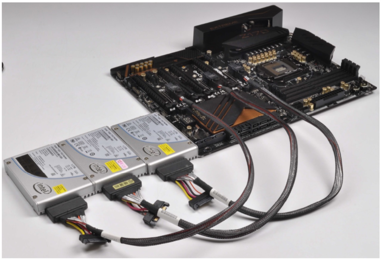
When we previously tested the SSD 750, it was noted that when the M.2 to U.2 adaptor was fitted to the motherboard, any double-slot graphics card that used the area near the second PCIe slot to place a long heatpipe going to the far end of the card (such as the GTX 770 Lightning we were using) was unable to be used in the slot above. In this instance, if you wanted to use three of these drives, then GPUs would have to be in the second long PCIe slot or the last slot on the board, which would remove SLI compatibility. So if this is a configuration you might be thinking of, then check your graphics cards can actually fit in the top slot. Some motherboards are starting to be released with U.2 ports where the SATA ports are, which solves the problem.
| ASRock Z170 Extreme7+ | |
| Warranty Period | 3 Years |
| Product Page | Link |
| Price | Amazon US |
| Size | ATX |
| CPU Interface | LGA1151 |
| Chipset | Intel Z170 |
| Memory Slots (DDR4) | Four DDR4, Supporting 64GB, Dual Channel, Up to 3600 MHz |
| Memory Slots (DDR3L) | None |
| Video Outputs | HDMI DisplayPort DVI-D |
| Network Connectivity | Intel I219-V Intel I211-AT |
| Onboard Audio | Realtek ALC1150 |
| PCIe Slots for Graphics (from CPU) | 3 x PCIe 3.0 (x16, x8/x8, x8/x4/x4) - PCIe 2/4/6 |
| PCIe Slots for Other (from PCH) | 1 x PCIe 3.0 x4 (PCIe 3) 1 x PCIe 3.0 x1 (PCIe 5) 1 x PCIe 2.0 x1 (PCIe 1) 1 x Half-Height Mini-PCIe |
| Onboard SATA | Six from Chipset, RAID 0/1/5/10 Four from ASM1061 |
| Onboard SATA Express | Three, RAID (shares with M.2) |
| Onboard M.2 | 3 x PCIe 3.0 x4 or SATA, RAID 0/1, NVMe |
| Onboard U.2 | None |
| USB 3.1 | 1 x Type-A + 1 x Type-C (ASMedia ASM1142) USB 3.1 Front Panel bundled, 1xA + 1xC via SATA Express |
| USB 3.0 | 4 x Rear Panel (Z170) 4 via headers (ASM 1074 hub) |
| USB 2.0 | 2 x Rear Panel 6 via headers |
| Power Connectors | 1 x 24-pin ATX 1 x 8-pin CPU |
| Fan Headers | 2 x CPU (4-pin) 4 x CHA/SYS (4-pin) |
| IO Panel | 1 x Combination PS/2 2 x USB 2.0 4 x USB 3.0 1 x USB 3.1 Type-A 1 x USB 3.1 Type-C 2 x Network RJ-45 HDMI DisplayPort DVI-D Audio Jacks |
| Other Features | Thunderbolt Header Power/Reset Buttons TPM Header Two-Digit Debug Display Clear CMOS Button BIOS Selection Switch Front Panel Header Front Audio Header COM Header |
Rather than continually ranting on about M.2 to U.2, the rest of the motherboard gives dual Intel network ports (I219-V and I211-AT), an enhanced Realtek ALC1150 audio codec solution, two USB 3.1 ports on the rear, a total of eight USB 3.0 ports (four on rear from the chipset, two headers onboard from a hub) and six fan headers all-in.
In The Box
We get the following:
Driver DVD
User Manual
Rear IO Shield
2-way SLI Bridge
USB 3.1 Front Panel
SATA Express Cable
USB 2.0 Header Cable (for panel)
Four SATA Cables
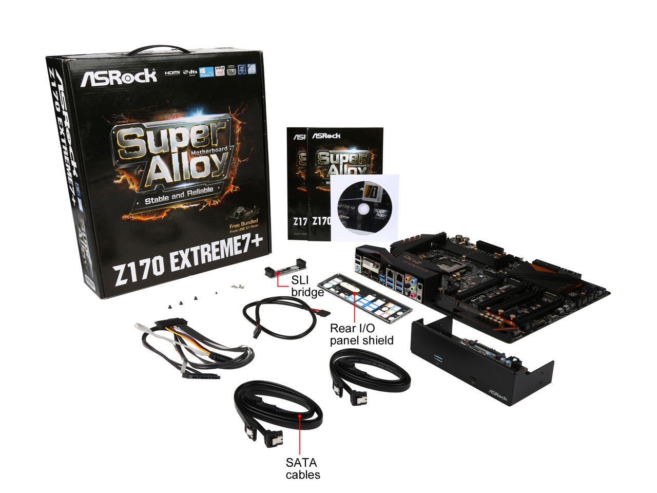
The USB 3.1 front panel is going to be the biggest thing to notice, followed closely by the SATA Express and USB 2.0 header cables needed to connect it together. Only one SLI bridge is included, presumably to keep costs low. As this is not a gaming branded board, we don’t see any extra Fatal1ty gubbins to entice end-users usually associated with that brand.
Visual Inspection
When taking the motherboard out of the box, it certainly feels like it has a good amount of mass compared to some flimsy alternatives. That mass is visible by looking at the board, showing a 12+2 power delivery with connected heatsinks on two sides of the socket and a rear panel shield stretching from top to bottom to provide both an aesthetic and an EMI shield. The chipset heatsink is also large compared to some others, used for a number of controllers underneath, and the styling continues using non-horizontal lines.
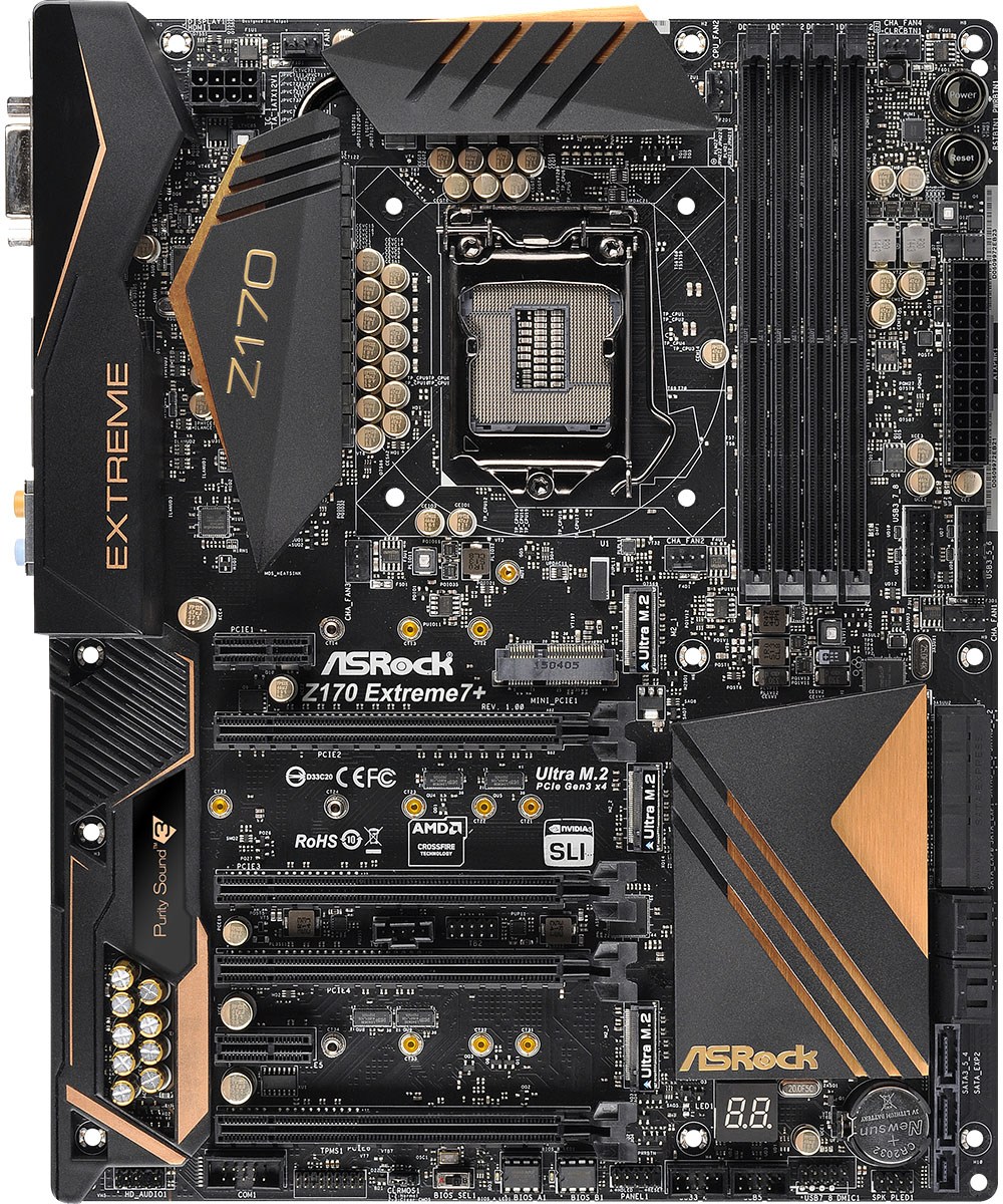
The PCB itself looks fairly busy, a common trait of ASRock boards, although it is clear that ASRock is using a decent quality board. The Extreme7+ is built for casual and prosumers in mind, hence we see relatively few onboard options for overclocking or extreme overclocking, but there are power and reset buttons in the top right for quick and dirty power management, and a two-digit debug on the bottom of the board for error codes.
The socket has all six 4-pin fan headers within easy reach – one in each corner of the socket (CPU_1 on the top left, CPU_2 on the top right), with another on the top right of the board next to the DRAM and another below the USB 3.0 headers on the right and in the middle of the board.
Moving counter clockwise, below the 24-pin ATX connector are two USB 3.0 headers powered by an ASMedia hub, so it is worth noting that bandwidth will be shared between these headers. On the SATA side of things there are two SATA Express ports in a regular position, featuring four of the SATA ports as well. This is followed by four SATA ports from an ASMedia ASM1061 controller, and then coming out of the motherboard is another SATA Express port containing two SATA ports, making ten SATA ports in total.
On the bottom of the board, from right to left, is an open USB 2.0 header, two closed off USB 2.0 headers (can be used for the USB 3.1 front panel), the two-digit debug display, the front panel header, the two BIOS chips, a BIOS select switch, a ClearCMOS header, a TPM header, the COM header, and finally the front audio header.
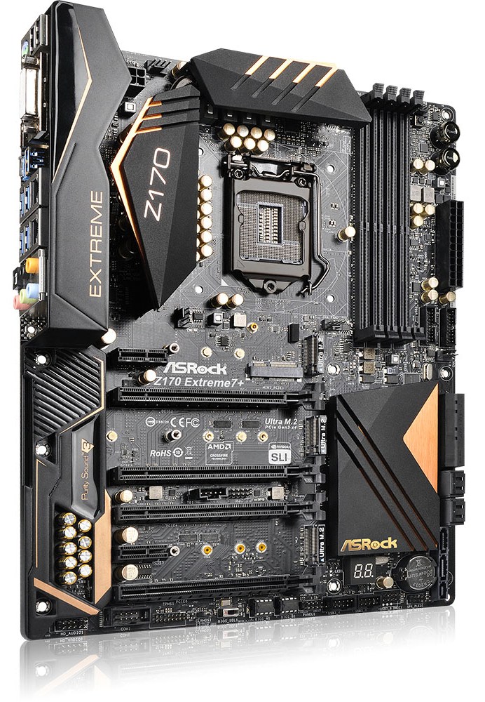
Now we come to the Eton Mess of ‘where are those PCIe lanes’ in the middle of the board. We have a mix of PCIe slots from the processor, PCIe slots from the chipset, M.2 slots from the chipset, and a mini-PCIe to add a cherry on top. Here’s a poorly drawn diagram drawn by my cat in MSPaint:
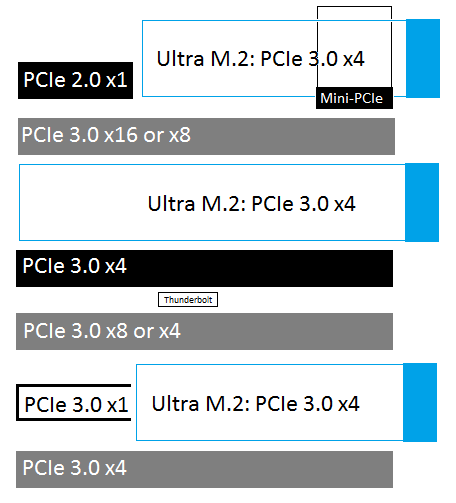
Here, the gray PCIe slots are from the CPU and are designed for graphics cards or high performance co-processors that need a PCIe x8 link or above. The slots in black (x1, x4, mini-PCIe and the open-ended x1 near the bottom) are from the Z170 chipset. The Ultra M.2 slots in blue, capable of a PCIe 3.0 x4 link and are Intel RST capable, are also from the chipset. Exact configurations of what works when (especially when SATA Express is in the mix) are found in the manual. To the left of the PCIe slots is the bottom part of the IO shield, which acts as a secondary EMI shield for the enhanced Realtek ALC1150 audio solution.

On the rear panel, by virtue of moving any BIOS buttons away, there are a healthy number of other features here. Two USB 2.0 ports along with four USB 3.0 ports, but in the middle is a USB 3.1 combination plinth with a Type-A and Type-C port in tow, both of which are powered by an ASMedia ASM1142 controller. For legacy we have a combination PS/2 port on the bottom left, and video outputs come via HDMI, DP1.2 and DVI-D ports. The two Intel network ports are also present, and at the end are the audio jacks.
Test Setup
| Test Setup | |
| Processor | Intel Core i7-6700K (ES, Retail Stepping), 91W, $350 4 Cores, 8 Threads, 4.0 GHz (4.2 GHz Turbo) |
| Motherboards | ASRock Z170 Extreme7+ |
| Cooling | Cooler Master Nepton 140XL |
| Power Supply | OCZ 1250W Gold ZX Series Corsair AX1200i Platinum PSU |
| Memory | Corsair DDR4-2133 C15 2x8 GB 1.2V or G.Skill Ripjaws 4 DDR4-2133 C15 2x8 GB 1.2V |
| Memory Settings | JEDEC @ 2133 |
| Video Cards | ASUS GTX 980 Strix 4GB MSI GTX 770 Lightning 2GB (1150/1202 Boost) ASUS R7 240 2GB |
| Hard Drive | Crucial MX200 1TB |
| Optical Drive | LG GH22NS50 |
| Case | Open Test Bed |
| Operating System | Windows 7 64-bit SP1 |
Readers of our motherboard review section will have noted the trend in modern motherboards to implement a form of MultiCore Enhancement / Acceleration / Turbo (read our report here) on their motherboards. This does several things, including better benchmark results at stock settings (not entirely needed if overclocking is an end-user goal) at the expense of heat and temperature. It also gives in essence an automatic overclock which may be against what the user wants. Our testing methodology is ‘out-of-the-box’, with the latest public BIOS installed and XMP enabled, and thus subject to the whims of this feature. It is ultimately up to the motherboard manufacturer to take this risk – and manufacturers taking risks in the setup is something they do on every product (think C-state settings, USB priority, DPC Latency / monitoring priority, overriding memory sub-timings at JEDEC). Processor speed change is part of that risk, and ultimately if no overclocking is planned, some motherboards will affect how fast that shiny new processor goes and can be an important factor in the system build.
For reference, the ASRock Z170 Extreme7, on our testing BIOS 1.4, MCT was not enabled by default. Also, the FCLK 10x ratio was not present in the BIOS at the time of testing, but is available on the newest BIOSes.
Many thanks to...
We must thank the following companies for kindly providing hardware for our test bed:
Thank you to AMD for providing us with the R9 290X 4GB GPUs.
Thank you to ASUS for providing us with GTX 980 Strix GPUs and the R7 240 DDR3 GPU.
Thank you to ASRock and ASUS for providing us with some IO testing kit.
Thank you to Cooler Master for providing us with Nepton 140XL CLCs.
Thank you to Corsair for providing us with an AX1200i PSU.
Thank you to Crucial for providing us with MX200 SSDs.
Thank you to G.Skill and Corsair for providing us with memory.
Thank you to MSI for providing us with the GTX 770 Lightning GPUs.
Thank you to OCZ for providing us with PSUs.
Thank you to Rosewill for providing us with PSUs and RK-9100 keyboards.


63 Comments
View All Comments
zeeBomb - Friday, November 27, 2015 - link
Whoa!!!dsumanik - Thursday, December 17, 2015 - link
AT Theres a typo in the headline, here's the correction:The ASRock Z170 Extreme7+ Review: When You Don't Test The Headline Feature Of The Motherboard.
Otherwise knows as: We didn't do our job, but trust us it's awesome and buy it anyways.
Seriously AT?
*Facepalm
daos - Friday, December 18, 2015 - link
I completely agree! Hasn't been the same since Anand leftpedjache - Friday, November 27, 2015 - link
In one of AT's previous articles, it was stated that the gtx770 used in tests gave odd results in Shadow of Mordor while the network connection was on, and said the matter will be looked into and reported. Anything on that?(more) on topic - nice review, wonderful motherboard, and kudos for praising them engineers, I happen to know they love and can't get enough of it.
Ian Cutress - Friday, November 27, 2015 - link
Still looking into it.flameyyy - Saturday, November 28, 2015 - link
do the DPC latency issues have anything to do with the bugged intel networking drivers? https://communities.intel.com/thread/54594evilspoons - Friday, November 27, 2015 - link
The Board Features/Visual Inspection page appears to be blank except for an introductory paragraph, as of 10:32 AM mountain time.evilspoons - Friday, November 27, 2015 - link
Also, it's a shame the headlining feature (triple M2 x4 in RAID) wasn't actually benchmarked. I would have loved to see 3x Samsung 950 Pro drives jammed in this sucker.eddieobscurant - Friday, November 27, 2015 - link
They will all share the same pci 3.0 x4 lanes, so there is a cap at 3.2 gb/s for the raid array. The thessdreview has a review of this combination.Flunk - Friday, November 27, 2015 - link
That's GB/s, which is 8x as much.