The GIGABYTE Z170X-Gaming G1 Review: Quad-SLI on Skylake, and now with Thunderbolt 3
by Ian Cutress on December 1, 2015 9:30 AM EST- Posted in
- Motherboards
- Gaming
- Intel
- Gigabyte
- PLX
- PLX8747
- Z170
- Thunderbolt 3
Board Features
The key features list for the Gaming G1 is a long one with multiple areas. From the top, alongside the 22-phase power delivery using IR controllers and chokes there is a combination air/water VRM heatsink, dual network ports (Killer E2400), 2T2R 802.11ac MU-MIMO WiFi (Killer AC-1535), a PLX chip to enable x16/x8/x8 or x8/x8/x8/x8 graphics arrangements, dual PCIe 3.0 x4 M.2 slots for storage, ten SATA ports, three SATA Express, USB 3.1 A+C on the rear powered by an Intel Alpine Ridge controller which has recently achieved certification for Thunderbolt 3 use on this motherboard, a bundled SATAe to USB 3.1 A+C front bay for additional ports and then there’s the enhanced audio subsystem with replaceable OP-AMPs and features like USB.DAC-Up which helps provide cleaner power to USB DACs.
| GIGABYTE Z170X-Gaming G1 | |
| Warranty Period | 3 Years |
| Product Page | Link |
| Price | Amazon US |
| Size | E-ATX (305x264 mm) |
| CPU Interface | LGA1151 |
| Chipset | Intel Z170 |
| Memory Slots (DDR4) | Four DDR4 Supporting 64GB Dual Channel Up to 3666 MHz |
| Memory Slots (DDR3L) | None |
| Video Outputs | HDMI 2.0 via LSPcon |
| Network Connectivity | 2 x Killer E2400 1 x Killer AC-1535 2T2R 802.11ac Dual Band |
| Onboard Audio | Creative Sound Core 3D + JRC NJM2114 + Burr Brown OPA2134 |
| PCIe Slots for Graphics (from CPU) | 4 x PCIe 3.0 via PLX8747 (x16/x16, x16/x8/x8, x8/x8/x8/x8) |
| PCIe Slots for Other (from PCH) | 3 x PCIe 3.0 x1 |
| Onboard SATA | Six, RAID 0/1/5/10 Four via ASM1061, no RAID |
| Onboard SATA Express | Three |
| Onboard M.2 | 2x PCIe 3.0 x4 or SATA, RAID 0/1, NVMe |
| Onboard U.2 | None |
| USB 3.1 | 1 x Type-A 1 x Type-C Intel Alpine Ridge Controller USB 3.1 Front Panel bundled, 1xA + 1xC via SATA Express |
| USB 3.0 | 4 x Rear Panel 2 via headers |
| USB 2.0 | 2 x Rear Panel 4 via headers |
| Power Connectors | 1 x 24-pin ATX 1 x 8-pin CPU |
| Fan Headers | 2 x CPU (4-pin) 5 x CHA/SYS (4-pin) |
| IO Panel | 1 x Combination PS/2 2 x USB 2.0 7 x USB 3.0 (4x PCH, 3 from Renesas Hubs) 1 x USB 3.1 Type-A 1 x USB 3.1 Type-C w/ TB3 Support (Update Required) 2 x Network RJ-45 HDMI 2T2R WiFi Antenna Audio Jacks Optical SPDIF Out |
| Other Features | Front Panel Header Front Audio Header 2 x USB 3.0 Headers (Renesas Hub) 2 x USB 2.0 Headers TP Header Clear CMOS Button Power/Reset Buttons ECO Button OC Button 2 x Audio Gain Control Switches BIOS Select Switch DualBIOS Switch Combination Air/Water Cooling VRM Heatsink 22-phase Power Delivery using IR Voltage Measurement Points |
A number of users will decry the use of Killer network ports over Intel ports based on their own expectations, or that the system includes XYZ which they will never use. But therein lies one issue that surrounds expensive flagship motherboards – to get the best value out of it, you have to use it all. So if a user ever wonders where the $500 they spent on the motherboard went, re-read the specification sheet, and look what came with it in the box as well.
In The Box
We get the following:
Driver CDs
User Manual
Rear IO Shield
Six SATA Cables
Wi-Fi Antenna
SATAe Cable for USB 3.1 Front Panel
USB 3.1 Front Panel
Two Long SLI Bridges
3-Way Rigid SLI Bridge
4-Way Rigid SLI Bridge
M.2 to U.2 adaptor
Quick Connector for Front Panel Cables
Rear IO Plastic Protectors

In order to get the most out of this package, you’ll need a good chunk of NVIDIA graphics cards, a large chassis, a few storage drives including one or two M.2/U.2 drives, need multiple network connections and own multiple USB 3.1 devices. One can dream for sure, or throw around the words ‘future-proof’.
Visual Inspection
At this point in time, GIGABYTE’s set of motherboard liveries are all very different, especially when we compare them to the past. We used to have blue and white on almost everything, then we saw some green on the G1 range, then orange for overclocking, then black and gold for the channel line, then full black for the server range. For the Gaming range this generation, we now go for a strong element of white with shades of red and black, because it seems red is the de facto color for gaming motherboards from 2013.
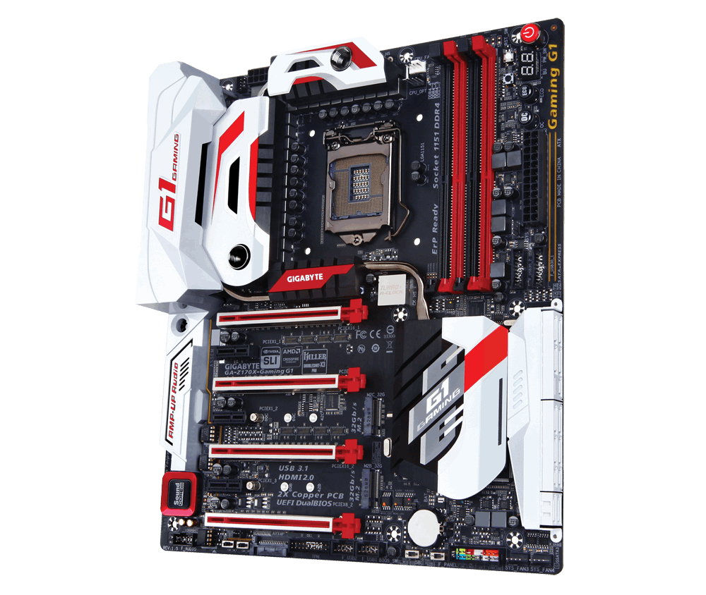
Like many of the other Z170 motherboards we’ve seen so far, the styling goes far to avoid rapid color changes over strictly horizontal barriers. I’m not sure if this has some psychological context, maybe because the PCIe slots are in that orientation by default. But a number of the motifs here are all at 45 degree angles.
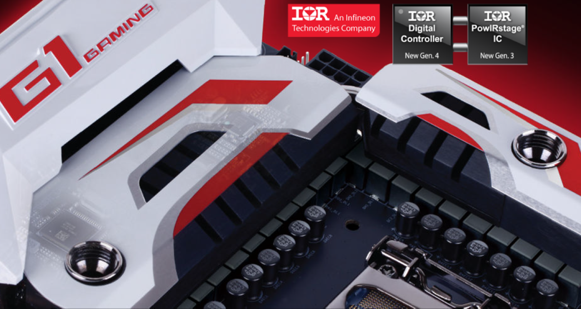
The socket area is hard to ignore – along with no white boxes for machine placement guides, the area is black and clear, presumably a not to users who want to insulate this area for sub-zero processor cooling. The socket is backed up by a 22-phase power delivery that combines controllers and chokes from International Rectifier – GIGABYTE were the first to use IR’s 60A voltage regulator modules back with Z77, and we had a hint back then that these cost $2 each. Given that there are 22 in total here, even if they were a 40A or 50A model that is still a fair chunk of BOM cost on power delivery alone. On top of these we have the power delivery heatsink which is connected to the PLX heatsink and the chipset heatsink via a heatpipe but also contains two connectors for water cooling, enabling an air/water cooling mix solution. These come with G1/4 threading fittings by default, and any equivalent barb or conversion kits that support G1/4 can be used.
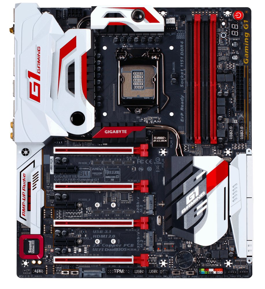
The socket has access to five of the seven fan headers on board, all of which are four-pin. The two CPU headers are above the socket and to the right as we look straight on, with one of these in white as the main CPU header and the black one is for any water cooling pump. There are two fan headers above the socket and two the left next to the 8-pin power connector, along with a header for the rear IO shield that offers customized lighting. The fifth fan header around the socket is just above the first PCIe slot on the left of the motherboard. The final two fan headers are on the bottom right of the board, below the SATA ports and chipset heatsink.

On the right hand side of the board are a few of the overclocking features and onboard buttons. Directly above the DRAM slots (to the right on the picture above, between the DRAM and the edge of the board) are a set of voltage read points. There is a small white switch which is a reset switch, a big red button for power, and a black button as a power switch to help completely reset the BIOS while still connected to power. This last point becomes useful if the system BIOS settings are too obscure to even allow entry, which can happen with extreme overclocking. There is also an obvious two-digit debug display, and to the left of this is an OC button for easy overclocking and an ECO button to put the board into a low power mode. Next to all of this is a long Gaming G1 logo on the PCB – this lights up when the system is powered on, and has a set of colors to choose from within the software.
Below the 24-pin ATX connector is a pair of USB 3.0 headers which come from a Renesas hub that splits a USB 3.0 port from the chipset into four, sharing bandwidth. The chipset heatsink as mentioned before is quite big but connected via heatpipes to the rest of the heatsinks. To the right of the chipset heatsink are the SATA ports with a total of ten which are also shared between three SATA Express connectors. These are also covered by what looks like an aesthetic shield, similar to the rear IO, but could also be acting as an EMI shield for components underneath.
On the bottom of the motherboard, from right to left, we have two of the fan headers, the front panel header (to be used with the boxed easy-connector provided), a switch to select between BIOS chips, a switch to enable DualBIOS, two USB 2.0 headers, a TPM header, a SATA power connector for the PCIe slots, two Audio Gain switches for the audio, a removable operational amplifier, the Burr Brown OPA2134 DAC and then a front panel audio header. The audio section in this bottom left uses a Creative Sound Core 3D chip along with additional filter caps, dual JRC NJM2114s, an EMI shield, PCB audio channel separation and other small tweaks to help improve the audio experience. The PCB separation is also fitted with LEDs which light up under use, and these can be controlled by part of GIGABYTE’s software package for Windows.
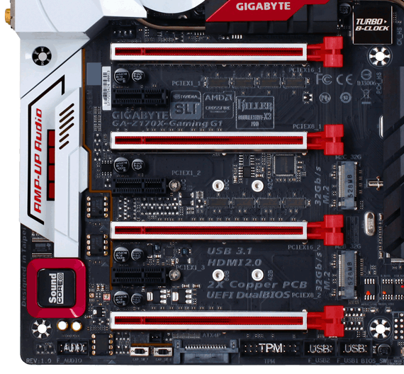
The PCIe slot arrangement on the Z170X-Gaming G1 is going to be a fairly rare one for the Z170 series for one main reason. Previously we saw most motherboard manufacturers using a PLX 8747 chip to bring quad-SLI using individual cards to the mainstream platform, and we even had a big review of four Z77 models explaining the technology. Between Z97 and Z170 however, the company behind making and selling the switches, PEX, was purchased by Avago. Avago has interests in supplying PCIe switches primarily to the server and enterprise markets who have bigger budgets, and almost overnight (or so we are to believe), the prices the chips made before the acquisition rose dramatically. Both the 8000-series here and the new 9000-series we reported on are both now aimed server side, and cost a fair whack. Back with Z77, we estimated they were around $40 each when bought in batches, with individual units costing $90+. I wouldn’t be surprised if the batch price was at least another 20-50% over that. There will be a number of server boards with this technology, such as the Z170 WS, which will also cost around the same price as the Gaming G1.
Nonetheless, on the Gaming G1 the PLX8747 switch multiplexes the sixteen PEG (PCI Express Graphics) lanes from the processor into 32, which are separated into two lots of sixteen for the first and third PCIe slots. These lots of sixteen also have additional basic switching, allowing for an x16/x0 or x8/x8 arrangement with the PCIe slot underneath. This gives an arrangement for x16/x0/x16/x0 to x8/x8/x8/x8, enabling a true four-way SLI rather than having to use dual-GPU based devices (or alternatively, with the right OS and compute workload, four dual GPU devices could be used). We have tested the PLX8747 in the past with PCIe 3.0 based gaming, only to find that the difference in performance for a single GPU was less than 1-2%, and within the margin for error.

The PCIe slots also have a bonded stainless steel shield with multiple anchor points over each graphics-focused PCIe slot. This helps with the mechanical rigidity when installing heavy graphics cards, as well as preventing damage when a random security airport check point decides to dismantle it without realizing there’s a lock release (I read it once on the internet, it was pretty brutal). Ultimately the hope is that it might reduce RMA incidents of this nature. In between the PCIe slots are a pair of M.2 slots which can both enable PCIe 3.0 x4 drives supporting NVMe, as well as RAID configurations under Intel’s RST. GIGABYTE also bundles a single M.2 to U.2 conversion adaptor for drives that support the U.2 standard.
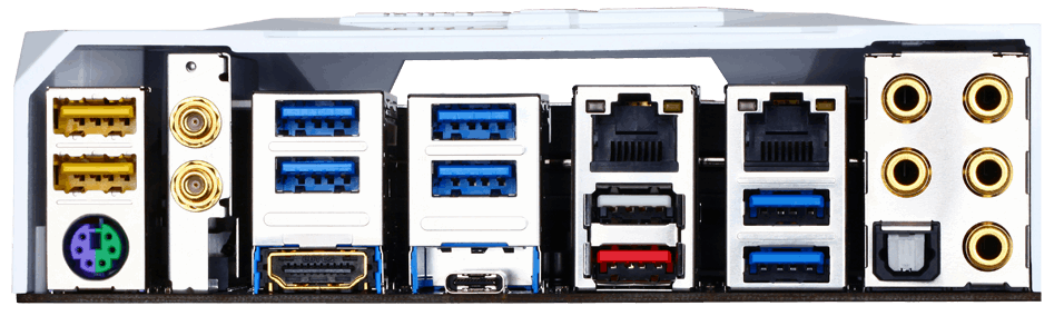
The rear panel is also covered by a white shield, maintaining the aesthetic for the motherboard. On the rear panel we get a pair of USB 2.0 ports, a PS/2 combination port, the 2T2R 802.11ac WiFi Killer 1535 card, HDMI output, a total of seven USB 3.0 ports (four from PCH, three from a Renesas hub to the PCH), two Killer E2400 network ports, a USB 3.1 Type-A running at 10 Gbps, a USB 3.1 Type-C running at 10 Gbps which also supports Thunderbolt 3 with the latest firmware, and at the end are gold plated audio jacks to reduce corrosion. The USB 3.1/TB3 ports are provided through Intel’s Alpine Ridge controller.
Test Setup
| Test Setup | |
| Processor | Intel Core i7-6700K (ES, Retail Stepping), 91W, $350 4 Cores, 8 Threads, 4.0 GHz (4.2 GHz Turbo) |
| Motherboards | GIGABYTE Z170X-Gaming G1 |
| Cooling | Cooler Master Nepton 140XL |
| Power Supply | OCZ 1250W Gold ZX Series Corsair AX1200i Platinum PSU |
| Memory | Corsair DDR4-2133 C15 2x8 GB 1.2V or G.Skill Ripjaws 4 DDR4-2133 C15 2x8 GB 1.2V |
| Memory Settings | JEDEC @ 2133 |
| Video Cards | ASUS GTX 980 Strix 4GB MSI GTX 770 Lightning 2GB (1150/1202 Boost) ASUS R7 240 2GB |
| Hard Drive | Crucial MX200 1TB |
| Optical Drive | LG GH22NS50 |
| Case | Open Test Bed |
| Operating System | Windows 7 64-bit SP1 |
Readers of our motherboard review section will have noted the trend in modern motherboards to implement a form of MultiCore Enhancement / Acceleration / Turbo (read our report here) on their motherboards. This does several things, including better benchmark results at stock settings (not entirely needed if overclocking is an end-user goal) at the expense of heat and temperature. It also gives in essence an automatic overclock which may be against what the user wants. Our testing methodology is ‘out-of-the-box’, with the latest public BIOS installed and XMP enabled, and thus subject to the whims of this feature. It is ultimately up to the motherboard manufacturer to take this risk – and manufacturers taking risks in the setup is something they do on every product (think C-state settings, USB priority, DPC Latency / monitoring priority, overriding memory sub-timings at JEDEC). Processor speed change is part of that risk, and ultimately if no overclocking is planned, some motherboards will affect how fast that shiny new processor goes and can be an important factor in the system build.
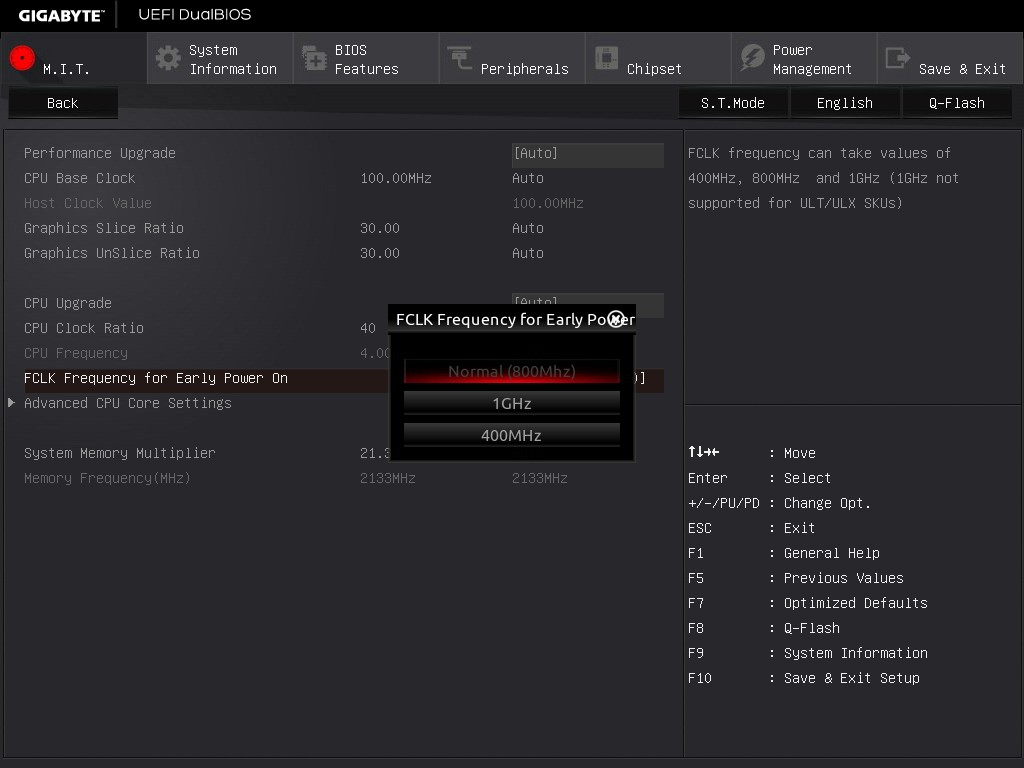
For reference, the GIGABYTE Z170X-Gaming G1, on our testing with BIOS F4p, MCT was enabled by default. Also, the FCLK 10x ratio was not present in the BIOS for this review, but is found in later version of the BIOS (we have a strict cut off policy when we start testing unless there’s a major flaw). To enable Thunderbolt 3, we suggest updating to the latest BIOS and ME version.
Many thanks to...
We must thank the following companies for kindly providing hardware for our test bed:
Thank you to AMD for providing us with the R9 290X 4GB GPUs.
Thank you to ASUS for providing us with GTX 980 Strix GPUs and the R7 240 DDR3 GPU.
Thank you to ASRock and ASUS for providing us with some IO testing kit.
Thank you to Cooler Master for providing us with Nepton 140XL CLCs.
Thank you to Corsair for providing us with an AX1200i PSU.
Thank you to Crucial for providing us with MX200 SSDs.
Thank you to G.Skill and Corsair for providing us with memory.
Thank you to MSI for providing us with the GTX 770 Lightning GPUs.
Thank you to OCZ for providing us with PSUs.
Thank you to Rosewill for providing us with PSUs and RK-9100 keyboards.


67 Comments
View All Comments
wperry - Tuesday, December 1, 2015 - link
Stopped reading at the first sentence. I'm sure it's snazzy and all, but no.ImSpartacus - Wednesday, December 2, 2015 - link
Yeah, I'm struggling to believe that Anandtech just formally recommended a $500 consumer motherboard.I know that the classic response will be, "well it's just a recommendation for those that want to spend that much money." But the problem is that the recommendation didn't say that in fine print. Those kinds of reasonable caveats don't make it on the "Anandtech recommended!" stickers that get put on the motherboard boxes.
It just seems weird.
samsonjs - Thursday, December 3, 2015 - link
Who needs to be told that it might be out of their price range? I think that's something people can figure out themselves.JVC8bal - Thursday, December 3, 2015 - link
No one needs a Ferrari or Bugatti. They're way overpriced for a car. But they are exemplar fetes of engineering. Believe it or not, there's people whom it doesn't matter whether they pay $20k or $2M for a car - it's a drop in the pan for them.Chad - Sunday, January 3, 2016 - link
Meh... just get the Gigabyte GA-Z170X-UD5 TH instead... almost all of the features at less than half the price.Zak - Tuesday, March 1, 2016 - link
Hey, but it's got three Krap NICs!Mikemk - Tuesday, December 1, 2015 - link
Looks awesome. The black DIMMs sortof strand out though, they should be wire.nathanddrews - Tuesday, December 1, 2015 - link
Which page tests the quad-SLI feature? I can't find it.DigitalFreak - Tuesday, December 1, 2015 - link
That's part of the problem with Anandtech (and review sites in general). The guy that does the MB reviews usually isn't the guy who does the GPU reviews, so he won't have access to the equipment to do those kind of tests.Ryan Smith - Tuesday, December 1, 2015 - link
And to be fair I don't even have 4 matching cards for quad-SLI. It's a very rare setup.